
Passive Audio Mixer
This simple line mixer has two drawbacks: it attenuates the signal all the time (even sliders set to maximum) and the output impedance is quite high. The first problem can be solved by just turning a little more volume in the amplifier. High output impedance is not a problem when connected to high impedance amplifier input with short wires (few meters). The dual logarithmic potentiometers are mechanically connected so that they move together, ensuring synchronized volume adjustments for left and right channels. This mechanical connection is achieved using dual potentiometers. If separate linear potentiometers are used, the sliders can be linked together through an appropriate method. For those preferring independent volume controls for each channel, separate potentiometers can be utilized without mechanical linkage.
The circuit allows for flexibility in connector types; 1/4" phone jacks can be used instead of RCA jacks without issues, provided they are wired correctly. Each input consists of two connections: for RCA connectors, the outer part connects to the common ground, while the center connects to the resistor. For phone jacks, the body connects to the common ground, and the tip connects to the resistor.
The schematic of the mixer circuit illustrates that the potentiometer sliders within the dual potentiometers are interconnected by a single line. Each input and output pin corresponds with a ground signal on the right side of the signal line. This design ensures a straightforward yet effective solution for mixing audio signals in various applications, particularly where portability and simplicity are key considerations.I designed this circuit for one friend of mine to be used as a small portable DJ mixer. The circuit is an audio mixer circuit so simple as it can be. There are two dual logarithmic potentiometers in the circuit to adjust the input signal levels and some resistors to do the actual mixing. The circuit is totally passive, so no power supply is needed. The circuit is suitable to be uses as a mixer between two line level sources and one HIFI amplifier input.
This circuit have been successfully used for mixing signals form two CD players or computer soundcard and CD players. There are many situations where simple mixer would be useful and commercially available mixer desks are too expensive and big.
This simple line mixer has two drawbacks: it attenuates the signal all the time (even sliders set to maximum) and the output impedance is quite high. The first problem can be solved by just turning a little more volume in the amplifier. High ouput impedance is no problem when connected to high impedance amplifier input with short wires (few meters).
That line means that those potentiometers are mechanically connected together so that they move together (that line does not mean any electrical connection because it is not connected to those potentiometers). This kind of mechanical connection is done in dual potentiometers. If you use two separate linear potentiometers then you can connect the sliders of them together using some suitable method.
If you prefer totally separate left and right channel volume controls then you don't need to do this mechanical connection between the potentiometers. Could I use 1/4" phone jacks as opposed to RCA jacks? Yes. No problems. You can use any line level signal connectors in the place of those RCA connectors when you wire them correctly to the circuit.
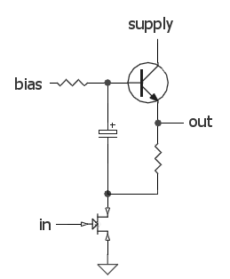
On each input, there are obviously two connections. To which part of the jack does each connect? For RCA connectors: Outer part in RCA connector goes to the common ground (right tap in schematic connections). The center of the RCA connector is connected to the resistor (left tap in schematic). For PHONE jacks: The body of the PHONE jack goes to common ground wire (right tap in schematic). PHONE connector tip then goes to the left tap in the schematic. In the picture below you see the schematic of the whole mixer circuit. The potentiometer slides which are actually inside one dual potentiometers are connected together using one line.
Every input and output pin has corresponding ground signal on the right side of the signal line. 🔗 External reference
Related Circuits
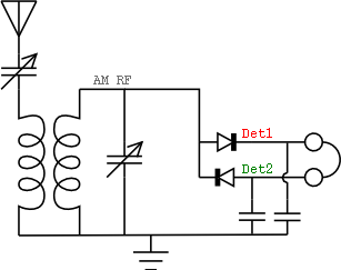
The concept of the passive receiver dates back over a century. The earliest known type of receiver capable of detecting radio energy is the coherer, which was invented by Edouard Branly. This primitive radio signal detector, used in the...
The input capacitor is used for low-frequency cut-off, with a standard value of 0.1 µF, resulting in a cut-off frequency of approximately 16 Hz. The input capacitor plays a crucial role in filtering unwanted low-frequency signals in electronic circuits. By...
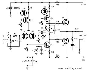
Designs for audio amplifiers with DC coupling to the load are not commonly seen today, despite their clear benefits. One advantage... Audio amplifiers utilizing DC coupling to the load present several notable advantages in specific applications. DC coupling allows for...
The audio source will be a line-level audio signal ranging from -2V to +2V AC, which will be passed through a 220µF coupling capacitor followed by a two-pole low-pass filter (RC). The signal will be processed by an Analog-to-Digital...
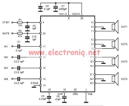
This circuit can be directly connected to CD players, tuners, and tape recorders. It requires the addition of a 10K logarithmic potentiometer (dual gang for stereo) and a switch to accommodate various sources. Proper grounding is crucial to eliminate...
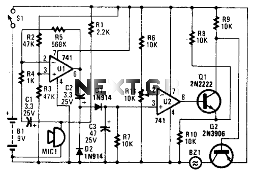
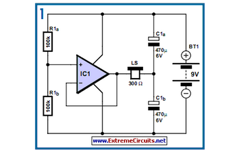
In the circuit, U1 amplifies the audio captured by the condenser microphone. Resistor R1 limits the current, while R2 and R3 center the amplifier's output to a voltage level of %B+ to facilitate the use of a single-ended power...