
4 Channel Portable Audio Mixer
The design of this portable mixer emphasizes modularity and adaptability, allowing users to configure the system to their specific requirements. Each Input Amplifier Module is designed to minimize noise, enhancing the overall audio quality. The variable gain feature allows for precise control over the input signal level, accommodating various microphone types and line-level sources. The Tone Control Module's three-band equalization enables users to tailor the audio output to their preferences, ensuring clarity and balance across different frequency ranges.
The mixer’s power consumption is remarkably low, making it suitable for battery-operated applications. This efficiency is especially beneficial for mobile setups, where power availability may be limited. The integration of the TL062 op-amp not only simplifies the design by reducing the number of components but also enhances performance through its dual-channel capabilities.
In terms of connectivity, the inclusion of various input and output options ensures compatibility with a wide range of audio equipment, facilitating seamless integration into existing setups. The use of a dual-gang potentiometer for the stereo line input allows for synchronized control of both channels, providing a user-friendly interface for volume adjustments.
Overall, this portable mixer design represents a sophisticated solution for audio mixing needs, combining high-quality performance with flexibility and low power consumption, making it an excellent choice for both amateur and professional applications.The target of this project was the design of a small portable mixer supplied by a 9V PP3 battery, keeping high quality performance. The mixer is formed assembling three main modules that can be varied in number and/or disposition to suit everyone needs.
The three main modules are: Input Amplifier Module: a low noise circuit equipped with a variabl e voltage-gain (10 - 100) preset, primarily intended as high quality microphone input, also suitable for low-level line input. Tone Control Module: a three-band (Bass, Middle, Treble) tone control circuit providing unity-gain when its controls are set to flat frequency response.
It can be inserted after one or more Input Amplifier Modules and/or after the Main Mixer Amplifiers. The image below shows a Block diagram of the entire mixer featuring four Input Amplifier Modules followed by four in-out switchable Tone Control Modules, one stereo Line input, four mono Main Faders, one stereo dual-ganged Main Fader, four Pan-Pots, a stereo Main Mixer Amplifier Module and two further Tone Control Modules switchable in and out for each channel, inserted before the main Left and Right outputs. Obviously this layout can be rearranged at everyone wish. An astonishing feature of this design lies in the fact that a complete stereo mixer as shown below in the Block diagram draws less than 6mA current!
The basic arrangement of this circuit is derived from the old Quad magnetic pick-up cartridge module. The circuit was rearranged to cope with microphone input and a single-rail low voltage supply. This low-noise, fully symmetrical, two-transistor head amplifier layout, allows the use of a normal FET input Op-Amp as the second gain stage, even for very sensitive microphone inputs.
The voltage-gain of this amplifier can be varied by means of R9 from 10 to 100, i. e. 20 to 40dB. The schematic of this circuit is drawn as a stereo unit to better show the input Main Fader and Pan-Pot connections. The TL062 chip contains two TL061 op-amps into the same 8 pin case and is wired as two virtual-earth mixer amplifiers having a voltage gain of about 4, to compensate for losses introduced in the passive Pan-Pot circuitry.
Therefore, total voltage-gain is 1. These parts must be wired as shown in the above circuit diagram, connecting R3 and R4 to pin #2 and pin #6 of IC1 for Right and Left channel respectively. These IC1 pins are the "virtual-earth mixing points" and can sum together a great number of channels.
To parts listed above should be added: one Main on-off SPST switch, a LED used as pilot-light with its dropping 2K2 1/4W series-resistor, DPDT switches to enable or omit Tone Control Modules as shown in the Block diagram, input and output connectors of the type preferred, one stereo dual-gang 100K potentiometer to fade the Stereo Line Input as shown in the Block diagram, battery clip, PP3 9V battery, knobs etc. 🔗 External reference
Related Circuits
The project involves the design of a custom multiplexer for a four-channel oscilloscope, allowing for simultaneous display of multiple figures with distinct X/Y inputs. The instrument is intended to enhance the functionality of existing oscilloscopes, particularly in conjunction with...
The philosophy behind this minimalist design has been explained by Flavio Dellepiane on his highly interesting site. I have myself written an article about this fleapower amp from Italy in the American magazine AudioXpress. All relevant details are published...
A 20-band equalizer for a 900-watt MOSFET power amplifier. The output level would decrease by the amount of resistors, so for two equal resistors, it should be amplified by a gain of 3. The first schematic is a simple...
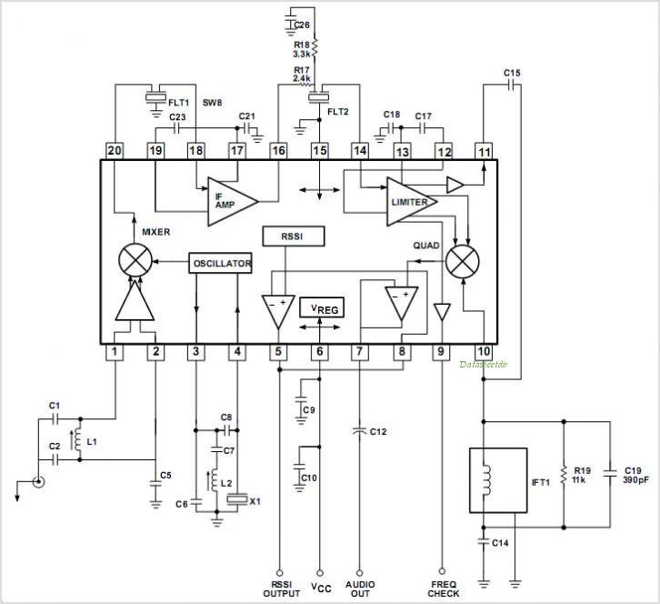
The SA9614 is an RF amplifier utilized for signal conversion and automatic laser power control (ALPC) between the CD optical pickup head and the decoding chip. The SA9614 incorporates an interface for the CD optical diode RF signal amplifier...
In a lot of cars, the car radios use amplifiers that their output power does not exceed the 5W with enough distortion in the limits of power. The problem is tied with the utilization of external amplifiers, that will...

This is a high-fidelity, high-quality audio amplifier circuit diagram. A pre-amplifier is not required. Component list: R1, R4 = 47K 1/4W resistors; R2 = 4.7K 1/4W resistor; R3 = 1.5K 1/4W resistor; R5 = 390Ω 1/4W resistor; R6 =...
Warning: include(partials/cookie-banner.php): Failed to open stream: Permission denied in /var/www/html/nextgr/view-circuit.php on line 713
Warning: include(): Failed opening 'partials/cookie-banner.php' for inclusion (include_path='.:/usr/share/php') in /var/www/html/nextgr/view-circuit.php on line 713