
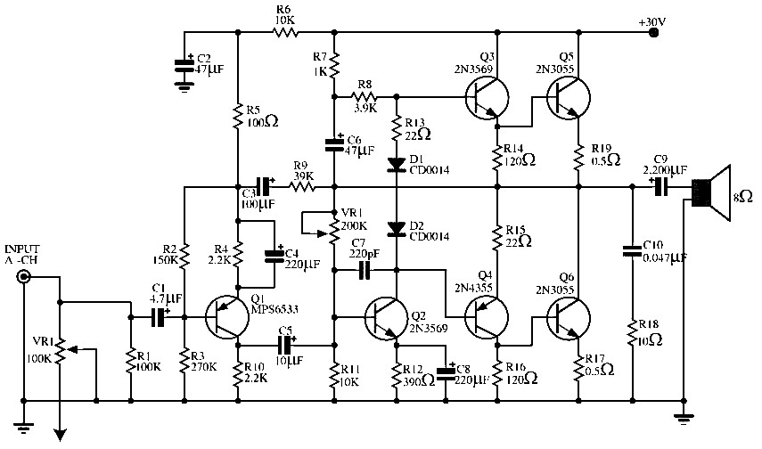
audio power amplifier circuit 140 w
No description available.
Related Circuits
Here is an amplifier circuit based on the BUZ11, which can be replaced by an IRFZ34N, and an ECC83 can be used instead of the ECC88. In this case, the anode voltage should be reduced slightly to 155 V....
Modify a zapper circuit (similar to the Hulda Clark Zapper) to produce two different frequencies. One switch should be used to set the pulse to 15Hz, and another switch to set it to 30Hz. The nominal frequency for this...
The following diagram is the circuit diagram of a 20W power amplifier built using the tube component EL34. The EL34 is a well-known tube, ideal for power tube amplifiers. The circuit presented is a complete design that includes both...
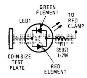
This circuit comprises a tri-color LED, a resistor, wire, and a coin-sized test plate. Two circuits must be constructed, one for each black clamp on a set of auto battery jumper cables. The circuits are installed inside the black...
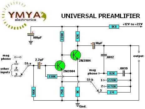
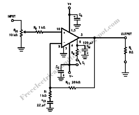
Most audio amplifier systems must have preamplifiers with many different characteristics. These include high-gain linear response for magnetic microphones, low-gain linear response for tuners, and high-gain RIAA equalization for magnetic phone cartridges. To meet this broad requirement, most amplifier...
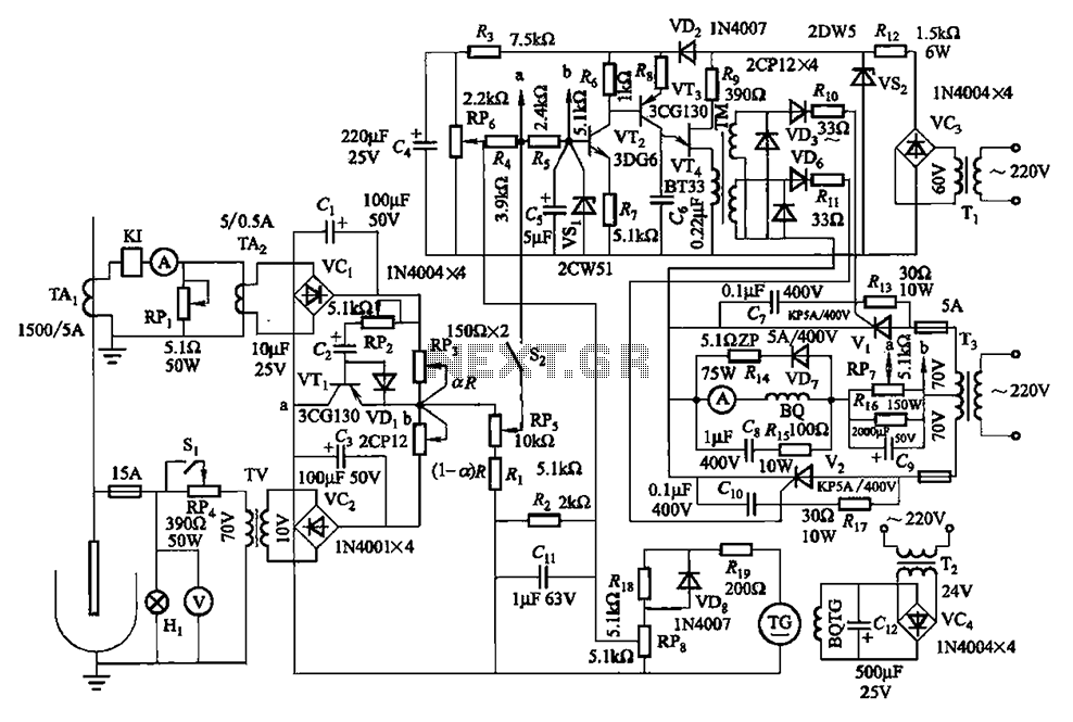
The circuit is illustrated in Figures 16-95 to 16-97. The electrode automatic adjuster demonstrates enhanced performance, featuring a high-accuracy, well-linear current output type bridge. Additionally, it incorporates a differential arc current negative feedback circuit (advanced) that allows for preemptive...