
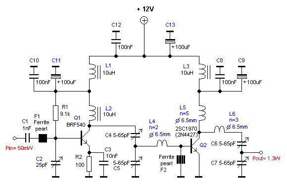
1.3W RF Amplifier Circuit
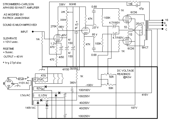
The 20W power amplifier circuit utilizing the EL34 tube is designed to deliver high-quality audio output. The circuit typically includes input and output stages, biasing networks, and feedback paths to enhance performance. The EL34 tube, known for its rich harmonic content, is suitable for audio applications where sound quality is paramount. The power supply circuit is crucial, as it provides the necessary voltage and current to the amplifier while ensuring stability and low noise.
The 16W audio amplifier circuit, based on the LM383 IC, is an example of a bridge amplifier configuration. This design allows for increased output power by utilizing both halves of the power supply. The use of alternative ICs, such as ECG1232 or TDA2002, ensures that the design remains viable despite the discontinuation of the LM383. The bridge configuration enhances efficiency and provides a more robust audio output.
The high-power 1500W amplifier circuit designed by Rod Elliott is a sophisticated design that requires careful thermal management due to the large number of transistors used. The MJ15024 and MJ15025 transistors are capable of handling significant power, making them suitable for high-performance audio applications. The power supply must be designed to accommodate the high current demands of the amplifier, ensuring that it can deliver clean power without distortion.
The "safari" amplifier, with its 400W output, is notable for its use of widely recognized transistors that are known for their reliability and performance in audio applications. The requirement for aluminum heatsinks is critical to prevent thermal overload and ensure the longevity of the components.
The thermocouple amplifier circuit using the CA3193 is designed for precision temperature measurement applications. The high gain of 500 ensures that even small signals generated by thermocouples can be accurately amplified for further processing. The inclusion of 22MΩ resistors provides a safeguard against open-circuit conditions, ensuring reliable operation.
Finally, the logarithmic amplifier circuit based on the LM11C is designed for applications requiring precise current measurements over a wide dynamic range. The unique frequency compensation and optional bias current compensation allow for high-resolution measurements, making this circuit suitable for various scientific and industrial applications.The following diagram is the circuit diagram of 20W power amplifier which build based tube component EL34. EL34 is very famous tube and great for power tube amplifier. The circuit above is complete circuit contains tube amplifier circuit diagram and power supply circuit diagram.
To make the stereo channel amplifier, build the similar amplifier cir cuit. The following diagram is 16W audio amplifier circuit. The circuit built based 2 pieces of power IC LM383 in bridge connection, so this amplifier is an bridge amplifier. This is an old amplifier, LM383 is discontinued, so this LM383 might be difficult to find. You can use ECG1232, TDA2002 or TDA2003 as the replace for. This is a very high 1500W power amplifier circuit diagram by Rod Elliott. The circuit is built using 10 pairs of power transistor MJ15024 and MJ15025 (or MJ21193/MJ21194), then it will use 20 pieces of power transistor for final amplification.
With very high power audio output, then of course it will need power supply with. This 400W power amplifier circuit often called as "safari" amplifier. The 400W power amplifier built using two couples of power transistors that are TIP31 with TIP32 and 2N3055 with MJ2955. These transistors are well known and widely used for the amplifier circuit and power supply circuit. Take a note that you must use aluminium heatsink. Above circuit design is thermocouple amplifier circuit using CA3193 operating amplifier. The CA3193 is an excellent choice for use with thermocouples. In the circuit, the CA3193 amplifies the generated signal 500 times. The three 22M © resistors will provide full-scale output if the thermocouple opens. The CA3193 are ultra-stable, precision instrumentation, operational amplifiers that employ. This is a logarithmic amplifier circuit based on National operational amplifier LM11C. Unusual frequency compensation provides this logarithmic converter a 100 µs time continual from 1 mA down to 100 µA, escalating from 200 µs to 200 ms from 10 nA to 10 pA.
Optional bias electric current compensation can give 10 pA resolution from. 🔗 External reference
Related Circuits
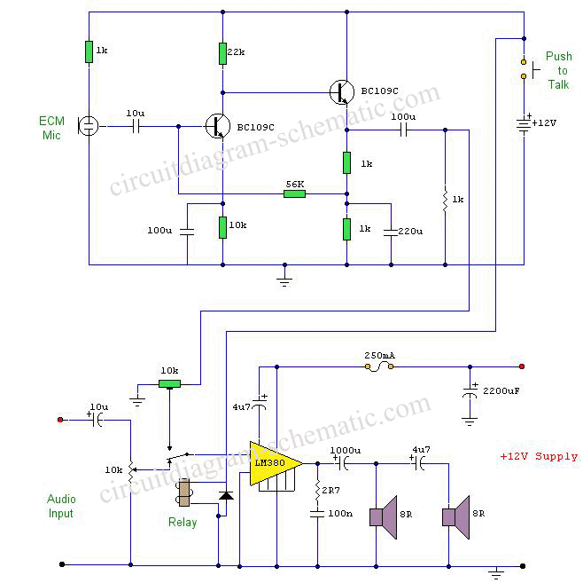
This circuit diagram represents a microphone preamplifier, specifically designed to prioritize voice signals over other audio inputs. In its basic configuration, the circuit includes a microphone unit and a change-over switch that connects to an amplifier. When the push-to-talk...
As the position of the sun changes, the illumination level on the light-dependent resistors (LDRs) also varies, causing the input voltage for the window comparator to deviate from half of the supply voltage. Consequently, the output of the comparator...
This microphone preamplifier utilizes the low-noise integrated circuit uA739. The circuit serves as an example of an effective preamplifier design for dynamic microphones. The integrated circuit contains two identical preamplifier circuits, with the second preamp functioning in the same...
The circuit above is a canonical AC coupled common emitter amplifier, which is typically used as a linear amplifier rather than a switch that activates when the input exceeds a certain level. The AC coupled common emitter amplifier is...
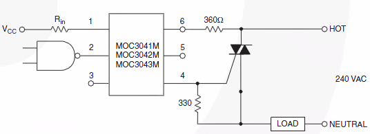
Switch 50V AC voltage. The maximum current drained will be 5A, with a frequency of 50Hz. The switching speed is not critical and can be slow, which is acceptable for the application. Initially, a solid-state relay (SSR) was considered...
If 40 watts RMS from 20Hz to 30KHz +/-1.5 dB is appealing, this experiment may be of interest. A significant issue with public address equipment is the use of audio output transformers that lack sufficient iron to manage lower...