
Audio power Amplifier Tester Dummy load
The described circuit functions as a dummy load for testing audio amplifiers. It is designed to simulate the electrical characteristics of a real speaker, thereby allowing for safe testing without risking damage to actual speaker components. The primary load resistor, R1, is rated at 8 ohms, which is a standard impedance value for many speakers, and is capable of handling up to 100 watts of power. An alternative value of 4 ohms is noted in parentheses, indicating that the circuit can also be configured to test amplifiers designed for lower impedance loads.
The circuit includes additional resistors, R2 and R3, which serve to modify the overall impedance and frequency response. R2 is specified as 39 ohms (with a secondary value of 18 ohms), rated for 5 watts, while R3 is 27 ohms (with a secondary value of 12 ohms), also rated for 5 watts. These resistors can help in fine-tuning the load characteristics to better match various amplifier designs.
Capacitance is provided by C1, a bipolar electrolytic capacitor rated at 200 microfarads, with a higher value of 400 microfarads listed in parentheses. This capacitor plays a crucial role in shaping the frequency response of the dummy load, allowing it to emulate the reactive nature of a real speaker.
Inductors L1 and L2 are included as part of the circuit to further refine the load characteristics. L1, with an inductance of 0.5 mH (or 0.25 mH), is rated for 3A and functions as a mains suppressor, helping to filter out high-frequency noise that could affect amplifier performance. L2, having an inductance of 25 mH (or 12 mH), also rated for 3A, serves a similar purpose, ensuring that the dummy load remains stable under various operating conditions.
This combination of resistive, capacitive, and inductive components allows the dummy load circuit to closely mimic the behavior of a real speaker, providing a safe and effective means of testing audio amplifiers without the risks associated with using actual speaker units.If you want to test an amplifier may be a dummy sometimes convenient for speakers to use than the actual speakers, due to noise or damage to the speakers. This circuit behaves in terms of impedance and frequency response as a real speaker and is calculated for a power of 100 watts into 8 ohms.
The value of 4 ohms is shown in parentheses. Parts List R1 = 8 ohms (4 ohms) 100 watts R2 = 39 ohm (18 ohm) 5 Watt R3 = 27 ohms (12 ohm) 5 Watt C1 = 200uF (400uF) bipolar Elko L1 = 0.5 mH (0.25 mH) 3A Triac / mains suppressor L2 = 25 mH (12 mH) 3A Triac / mains suppressor 🔗 External reference
Related Circuits
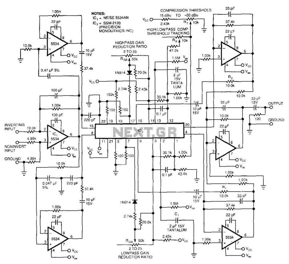
This 2-band compressor separates audio into high and low frequencies, allowing for independent adjustments of each band. Two active filters drive the two halves of a dual voltage-controlled amplifier/rectifier integrated circuit (IC). Each section features a dynamic range exceeding...
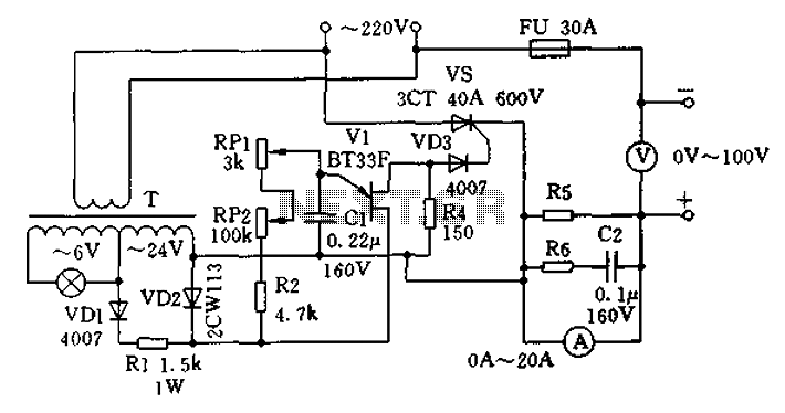
The charging apparatus depicted in the schematic circuit has a maximum output current of 20A and a maximum charging voltage of 80V. It can be adjusted starting from 0V, making it suitable for charging various types of batteries. The...
The aim of this design was to reproduce a Combo amplifier of the type very common in the sixties and the seventies of the past century. It is well suited as a guitar amplifier but it will do a...
A light-seeking solar-powered tiny robot based on a BEAM design. The article includes pictures, links, a video, and a schematic. The described robot employs a BEAM (Biology, Electronics, Aesthetics, and Mechanics) design philosophy, which emphasizes simple, efficient, and often analog...
Here I propose a project of an AB class power amplifier, at its simplest, assembled with common components (not very expensive), based on traditional diagrams: a symmetrical differential input stage, a cascode stage driver, and a MOSFET output stage....
The LM380 is a power audio amplifier designed for consumer applications. To minimize system costs, the gain is internally fixed at 34 dB. It features a unique input stage that allows for ground-referenced input signals. The output automatically self-centers...
Warning: include(partials/cookie-banner.php): Failed to open stream: Permission denied in /var/www/html/nextgr/view-circuit.php on line 713
Warning: include(): Failed opening 'partials/cookie-banner.php' for inclusion (include_path='.:/usr/share/php') in /var/www/html/nextgr/view-circuit.php on line 713