
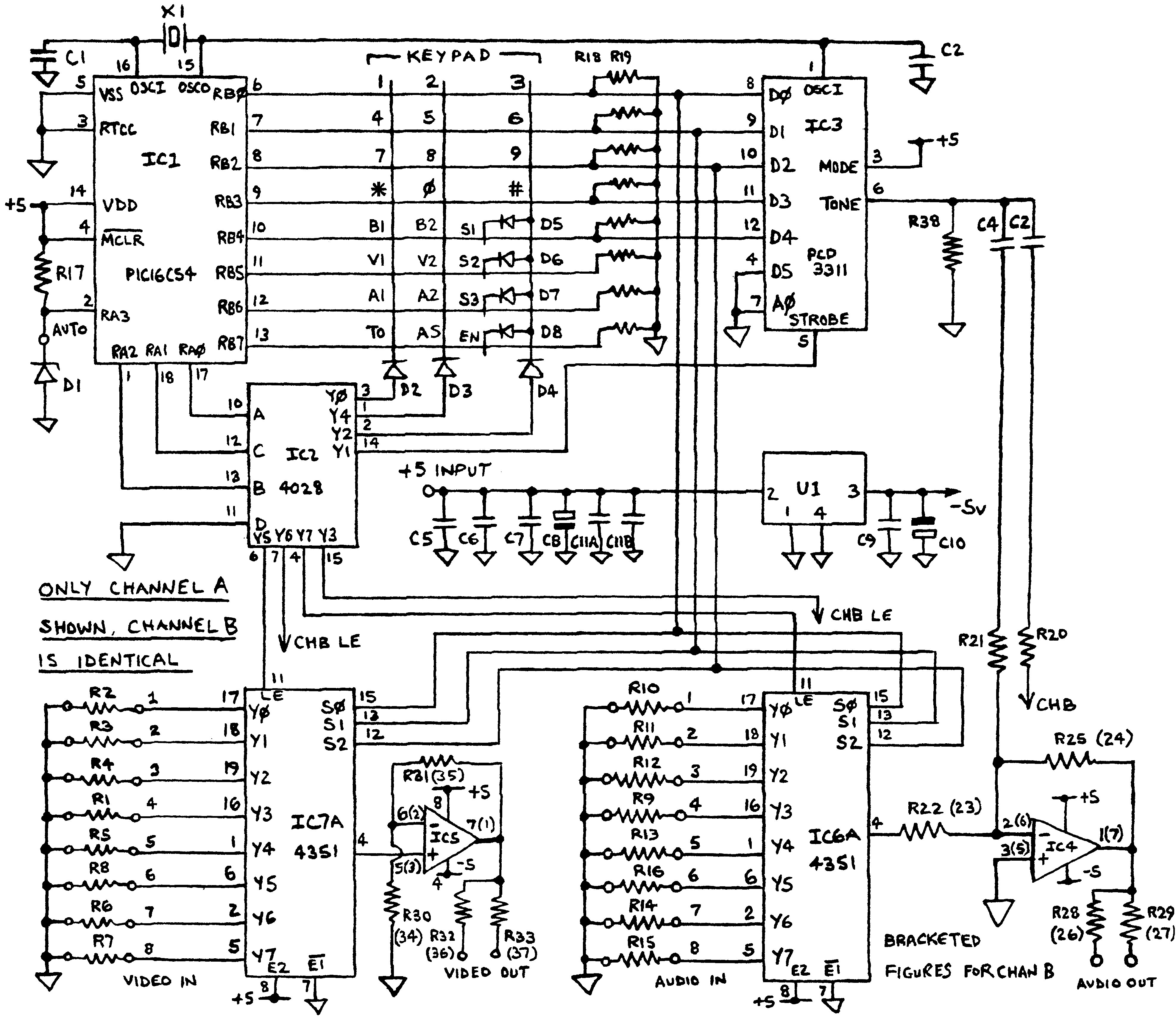
room noise detector circuit schematic
The circuit employs a miniature electret microphone as the primary sound sensing element. The microphone converts sound waves into electrical signals, which are then amplified by two operational amplifiers configured in a non-inverting gain configuration. This amplification is essential to ensure that the microphone's output is sufficient to drive the LED indicator effectively.
The operational amplifiers are powered by a dual supply voltage, which allows for a wide dynamic range and improved signal fidelity. The gain of the op-amps can be adjusted by changing the feedback resistors, allowing for fine-tuning of the sensitivity levels corresponding to the selected dB thresholds.
The threshold levels are set using a rotary switch (SW1), which connects different resistor values into the circuit to determine the sensitivity of the microphone. In the first position, the circuit is completely disabled, conserving power when not in use. In the second, third, and fourth positions, the circuit becomes active, with each position corresponding to one of the three noise threshold levels.
The LED serves as a visual indicator of the noise level. When the ambient noise exceeds the selected threshold, the op-amps output a signal that activates the LED. The LED will flash to indicate that the noise level is beyond the acceptable range, with the current consumption varying based on the state of the LED. In the off state, the circuit consumes approximately 1 mA, while in the active state with the LED illuminated, the current draw increases to between 12 mA and 15 mA, depending on the specific conditions and design of the circuit.
This circuit can be used in various applications, such as in sound-sensitive environments, noise monitoring systems, or as an educational project to demonstrate the principles of sound detection and signal processing. Properly designed, it can provide a reliable indication of noise levels, enhancing awareness of sound environments.This circuit is intended to signal, through a flashing LED, the exceeding of a fixed threshold in room noise, chosen from three fixed levels, namely 50, 70 & 85 dB. Two Op-amps provide the necessary circuit gain for sounds picked-up by a miniature electret microphone to drive a LED.
With SW1 in the first position the circuit is off. Second, third and fourth positions power the circuit and set the input sensitivity threshold to 85, 70 & 50 dB respectively. Current drawing is 1mA with LED off and 12-15mA when the LED is steady on.. 🔗 External reference
Related Circuits
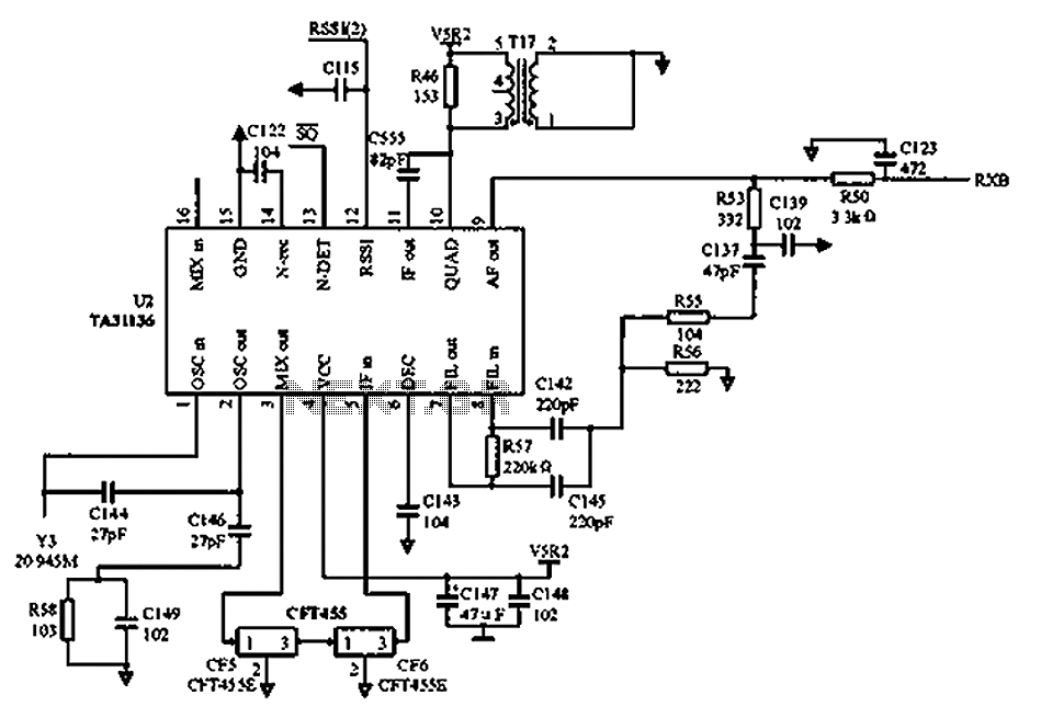
As illustrated in the figure, Vcc is the power supply for the circuit. Upon receiving the initial signal, the frequency is adjusted to 21.7 MHz. This frequency is subsequently enhanced through two crystal filters to improve the selectivity of...
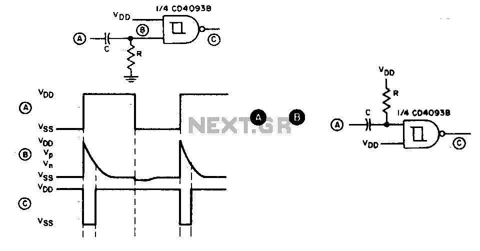
This circuit generates a brief negative-going output pulse in response to each positive-going edge at the input. The input signal is coupled to the circuit through a capacitor (C), and the duration of the output pulse is determined by...
A DIY GSM jammer schematic diagram designed for use with GSM1900, operating within the frequency range of 1930 MHz to 1990 MHz. The GSM jammer circuit is intended to disrupt communication between mobile phones and base stations within the specified...
Before applying power, check for shorts on the board. This design operates from a 5V supply; connecting it directly to a 12V supply will certainly damage it. The current draw is minimal, approximately 70mA, so if using a 12V...
The following circuit illustrates a Light Barrier Sensor Detector Circuit Diagram. Features include a single transistor, an adjustable potentiometer, and a 6V power supply. The Light Barrier Sensor Detector Circuit is designed to detect the presence of an object by...
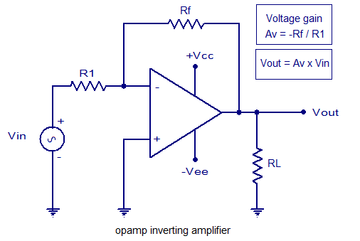
An inverting amplifier utilizing an operational amplifier (op-amp). This includes equations for voltage gain and output voltage, as well as input and output waveforms, and a practical inverting amplifier circuit using the 741 IC. An inverting amplifier is a fundamental...
Warning: include(partials/cookie-banner.php): Failed to open stream: Permission denied in /var/www/html/nextgr/view-circuit.php on line 713
Warning: include(): Failed opening 'partials/cookie-banner.php' for inclusion (include_path='.:/usr/share/php') in /var/www/html/nextgr/view-circuit.php on line 713