
MOSFET IRF510 Capacitor Discharge Ignition(CDI) Circuit and explanation
The described circuit functions primarily as a high-voltage ignition system, combining several key components to achieve efficient energy transfer and high-voltage output. The 2 µF capacitor serves as the energy storage element, charged to a high voltage to enable significant discharge. The SCR acts as a switch, allowing controlled release of the stored energy, while the Schmitt trigger oscillator generates the necessary control signals for the SCR and the MOSFET.
The 74C14 Schmitt trigger oscillator is designed to provide a stable square wave output, which is essential for driving the MOSFET, IRF510. The MOSFET operates as a low-voltage switch, controlling the power transformer that steps down the voltage from 120V AC to a lower level, suitable for the oscillator circuit. The voltage doubler circuit on the high-voltage side ensures that the voltage across the capacitor is maintained at the desired level, facilitating the ignition process.
During operation, the SCR is triggered by the Schmitt trigger oscillator at a frequency of four times per second, allowing for controlled discharges of the capacitor. The diode connected to the 3904 transistor plays a crucial role in ensuring that the power supply is disabled during the discharge phase, preventing accidental triggering of the SCR. The system is designed to operate efficiently, drawing minimal current from the power supply while delivering high voltage output.
The ignition coil's output voltage, reaching approximately 10 kV, is suitable for creating a spark across the specified spark gap. The design allows for adjustments in the spark rate, although limitations exist based on the transformer characteristics and oscillator duty cycle. For applications requiring higher spark frequencies, modifications to the power supply and oscillator design may be necessary.
Safety precautions are paramount when working with this circuit due to the high voltages involved. Grounding the ignition coil or using alternative configurations can help mitigate shock hazards, making the system safer for practical applications, particularly in automotive ignition systems.A 2uF capacitor is charged to regarding 340 volts and also the discharge is controlled by an SCR. A Schmitt trigger oscillator (74C14) and MOSFET (IRF510) are used to drive the low voltage aspect of alittle (120/12 volt) power transformer and a voltage doubler arrangement is employed on the high voltage aspect to extend the capacitor voltage to re garding 340 volts. an analogous Schmitt trigger oscillator is employed to trigger the SCR regarding four times per second. the ability provide is gated off throughout the discharge time so the SCR can stop conducting and come back to it`s blocking state.
The diode connected from the 3904 to pin nine of the 74C14 causes the ability provide oscillator to prevent throughout discharge time. The circuit attracts solely regarding two hundred milliamps from a twelve volt supply and delivers virtually twice the conventional energy of a standard ignition circuit.
High voltage from the coil is regarding 10KV employing a 3/8 in. spark gap at traditional air temperature and pressure. Spark rate may be increased to probably ten Hertz while not losing abundant spark intensity, however is restricted by the low frequency power transformer and duty cycle of the oscillator. For faster spark rates, the next frequency and lower impedance provide would be needed. Note that the ignition coil isn`t grounded and presents a shock hazard on all of it`s terminals. Use CAUTION when operating the circuit. An alternate methodology of connecting the coil is to ground the (-) terminal and relocate the capacitor between the cathode of the rectifier diode and also the positive coil terminal.
The SCR is then placed between ground and also the +340 volt aspect of the capacitor. This reduces the shock hazard and is that the usual configuration in automotive applications. 🔗 External reference
Related Circuits
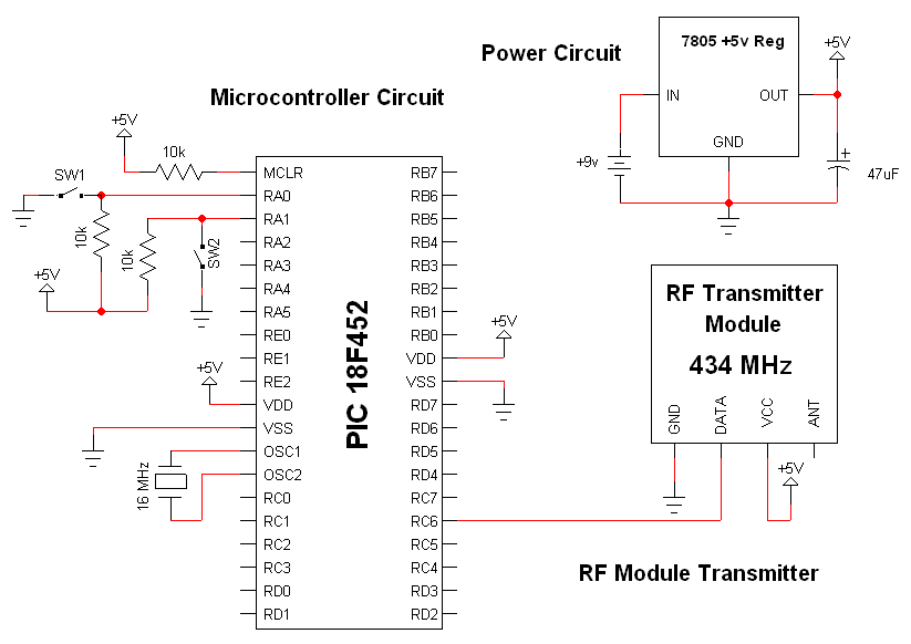
The RF modules utilized in this schematic are straightforward, requiring only a few additional pins for power, ground, and data connections. The primary components featured in this schematic include the RF transmitter module, the RF receiver module, and the...
Although labelled as distortion, this is a soft clipping device, using germanium diodes. It's a good example of how little you need for a good basic sound. You could easily swap (or switch) these diodes to silicon types for...
A video digitizer, also known as a frame grabber, captures images from a television set, camera, or video recorder and sends them to a computer for display, storage, or manipulation. This document describes a home-built digitizer that connects to...
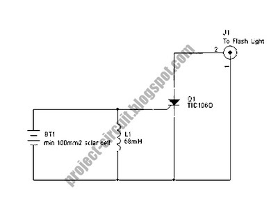
The following circuit illustrates a Slave Flash Light Control Circuit Diagram. Features include a 68 mH inductor, which provides an automatic trigger for the secondary flash light. The Slave Flash Light Control Circuit is designed to enhance the functionality of...
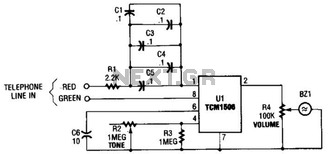
The circuit utilizes the TCM1506 ring detector/driver integrated circuit, which is a monolithic IC designed to replace mechanical bells in telephones. It is powered and activated by the telephone line's ringing signal, which ranges from 40 to 150 V...
Crystal Y1 generates a fundamental frequency clock signal of 14.31818 MHz. U31 is a Dual Voltage Controlled Oscillator (VCO) that produces a 14.31818 MHz clock signal, referred to as the color clock, at pin 10. The output frequency can...