
Bearing fault detector circuit diagram 2
The bearing fault detection circuit is designed to monitor the operational integrity of bearings by detecting faults through various components that work in unison. The circuit begins with the bearing detection sensors that capture data regarding the condition of the bearings. These sensors are critical for identifying anomalies such as vibrations or temperature changes that may indicate wear or failure.
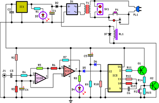
The signal processing circuit serves as the central hub for interpreting the data from the sensors. It includes an input socket (XS) for receiving signals, a voice integrated circuit (IC1) that processes audio signals, and several passive components like capacitors (C1, C2, C3) and resistors (R1, R2). The potentiometer (RP) allows for fine-tuning of the circuit's response characteristics, ensuring accurate detection thresholds.
The sound and light circuit is responsible for providing feedback to the user regarding the status of the bearings. It utilizes transistors (V1, V2) to control the activation of visual indicators (LEDs VL1, VL2) and auditory signals through an audio power amplifier (IC2). The use of resistors (R3, R4) and a capacitor (C4) in this circuit helps to manage current flow and signal clarity. Diodes (VD1, VD2) are included to protect the circuit from potential back EMF generated by the speaker (BL), ensuring longevity and reliability.
Overall, this circuit is a comprehensive system for real-time monitoring of bearing health, employing a combination of sensor technology, signal processing, and user feedback mechanisms to ensure operational safety and efficiency. Proper selection of components, such as metal film resistors and a synthetic membrane potentiometer, contributes to the circuit's performance and durability.The bearing fault detection circuit is composed of the bearing detection sensors, signal processing circuit and sound and light circuit, and it is shown as the chart. Signal processing circuit consists of the input socket XS, voice integrated circuit IC1, capacitors C1 ~ C3, resistors R1, R2 and potentiometer RP.
Sound and light is composed of the transistors V1, V2, LEDs VL1, VL2, audio power amplifier integrated circuit IC2, resistors R3, R4, capacitor C4, diodes VD1, VD2, and speaker BL. R1 ~ M select the 1/4W or 1/8W metal film resistors. RP uses the small synthetic membrane potentiometer or variable resistor. 🔗 External reference
Related Circuits
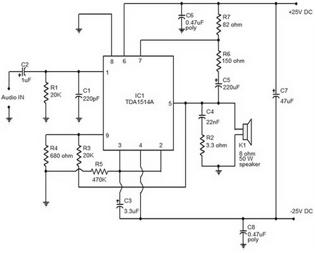
This document provides a circuit diagram of a car stereo. It includes a circuit diagram of a Class B 15 Watts audio amplifier designed using a dual op-amp and a transistor. The 15 W Class B audio amplifier circuit...
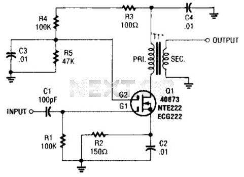
A MOSFET is utilized as a wideband buffer amplifier. T1 is wound on a toroid of approximately specified diameter, using material suitable for the frequency range, typically between 1 MHz and 20 MHz. The turns ratio should be approximately...
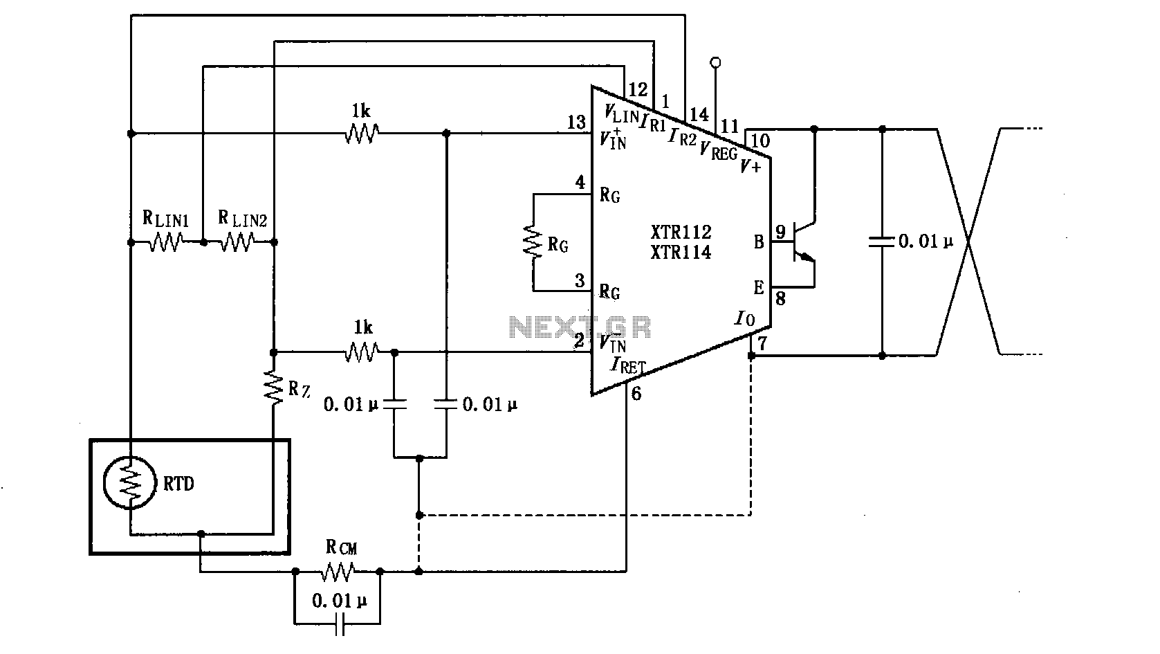
The length of the transmission wire in a current loop circuit can introduce radio frequency (RF) interference. This RF energy may lead to input errors in sensitive devices such as the XT112/114, causing instability in loop current or input...
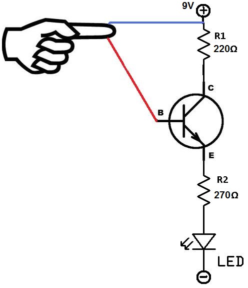
This project utilizes two wires, one red and one blue, which function as touch sensor wires. When a person touches both wires, the circuit closes, allowing current to flow and illuminate the LED. A 9-volt battery or an external...
This compact circuit is designed to be cost-effective, particularly useful during instances when the power supply is interrupted, such as while taking a shower. The backup lamp remains off as long as the CdS photocell is exposed to light...
This circuit deactivates an amplifier or any connected device when a low-level audio signal at its input is absent for at least 15 minutes. Pressing P1 turns the device on, supplying power to any appliance connected to SK1. The...
Warning: include(partials/cookie-banner.php): Failed to open stream: Permission denied in /var/www/html/nextgr/view-circuit.php on line 713
Warning: include(): Failed opening 'partials/cookie-banner.php' for inclusion (include_path='.:/usr/share/php') in /var/www/html/nextgr/view-circuit.php on line 713