
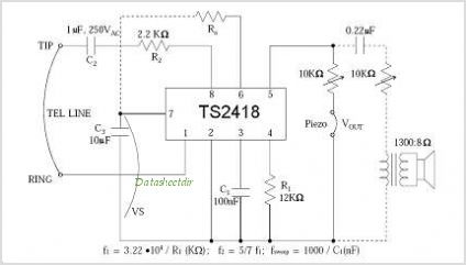
Telephone off-hook indicator
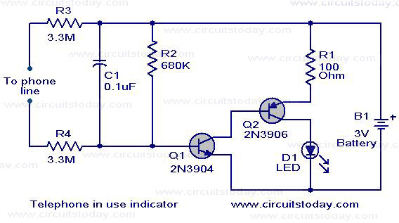
The circuit utilizes a complementary Darlington pair configuration to amplify the current generated when the telephone receiver is lifted off the hook. The 2N3904 NPN transistor (Q1) and the 2N3906 PNP transistor (Q2) work in tandem to provide high sensitivity and low power consumption.
When the telephone receiver is off-hook, the current flows through the telephone line, activating Q1. This, in turn, allows current to flow to Q2, which drives the LED. The LED serves as a visual indicator, illuminating to signal that the receiver is in use.
The circuit can be powered from the telephone line itself, which typically supplies a small voltage sufficient for the operation of the transistors and the LED. Resistors may be used to limit the current through the LED and to set the biasing conditions for the transistors, ensuring they operate within their safe limits.
In summary, this circuit provides a practical solution for older telephone systems, enhancing functionality by adding an off-hook indicator without requiring significant modifications to the existing setup. It exemplifies a straightforward yet effective application of transistor technology in telecommunication devices.The circuit depicted here can be used as an indicator when the telephone receiver is off-hook. The circuit can be in corporated with old telephones that does not have such an indicator. The circuit uses a complementary darling to pair using Q1 (2N3904)and Q2 (2n3906) to sense whether the receiver is off hook and glows a LED to show the condition. 🔗 External reference
Related Circuits
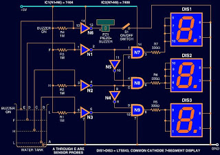
Circuits designed to indicate water levels typically consist of LEDs to represent the liquid level. However, this circuit utilizes a 7-segment LED display instead of standard LEDs for a numeric representation of the water level. Additionally, a buzzer is...
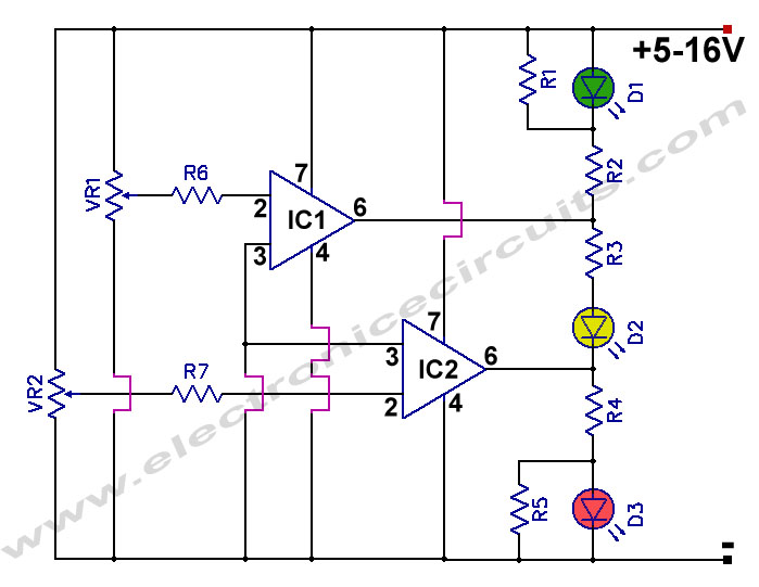
12V Battery Charge Nominal Discharge (Low) Indicator Circuit. This circuit monitors car battery voltage and provides an indication of nominal levels. The 12V Battery Charge Nominal Discharge Indicator Circuit is designed to monitor the voltage levels of a car battery...
The circuit automatically lights a bulb upon the arrival of a telephone ring and simultaneously mutes the audio from the music system or TV while the telephone handset is off-hook. The lighting of the bulb not only indicates an...
It uses old pulse dial handsets and replaces the AC bell set with a 9 volt DC buzzer. The whole circuit runs from a 12 volt regulated DC supply and is suitable for short term battery operation (eg: Gel...
In order to generate a single note you may try these simple circuits. With only three components you may implement some basic buzzers. You need a telephone earpiece for the first circuit. Any old telephone set has got one...
The TS4956 is a comprehensive audio system device featuring three dedicated outputs: one for stereo headphones, one for loudspeaker drive, and one mono output for a hands-free set. The stereo headphone output can deliver over 25 mW per channel...