Audio signal Indicator

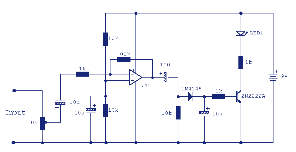
This circuit can be used to remotely monitor a loudspeaker, alarm, or audio source for presence of an audio waveform. It can also be directly connected across loudspeaker terminals used as a peak indicator. If you need to monitor some audio signal at a location that is either soundproof or too far away to actually hear the signal, then you can use a circuit similar to this one. A remote indication that the audio source is active is provided visually, here in the form of a LED. Referring to the above circuit, the 10k preset is a level control which should be adjusted so that when the source (audio signal or alarm) is producing the desired amount of noise, the LED lights. The input stage is an inverting x100 amplifier made with a 741 op-amp. The output of the 741 is capacitively coupled into a 10k load resistor, thus removing any dc component from the signal and the offset null voltage of the op-amp.
This circuit functions as an audio presence indicator, enabling remote monitoring of audio signals such as those from loudspeakers or alarms. It is particularly useful in scenarios where the monitoring location is either soundproof or at a considerable distance from the audio source, making direct auditory monitoring impractical.
The circuit employs a 741 operational amplifier configured as an inverting amplifier with a gain of 100, which amplifies the input audio signal significantly. The choice of the 741 op-amp is notable due to its low noise characteristics and adequate bandwidth for audio applications. The input signal is fed into the inverting terminal of the op-amp, while the non-inverting terminal is grounded.
To ensure that only the AC component of the audio signal is processed, the output of the op-amp is capacitively coupled to a load resistor. This coupling capacitor blocks any DC offset that may be present in the audio signal, thereby allowing only the AC waveform to pass through. The subsequent 10kΩ resistor serves as a load, and it is critical for setting the output impedance of the amplifier stage.
A 10kΩ preset potentiometer is integrated into the circuit to provide adjustable sensitivity. This allows the user to calibrate the circuit so that the LED indicator activates at the desired audio signal level. When the audio source produces sufficient sound, the amplified signal triggers the LED, providing a clear visual indication of audio activity.
The design of this circuit is both simple and effective for audio monitoring applications, and it can be adapted for various audio sources by adjusting the gain and sensitivity settings. Additionally, the circuit’s low power consumption and compact size make it suitable for integration into portable monitoring systems.This circuit can be used to remotely monitor a loudspeaker, alarm, or audio source for presence of an audio waveform. It can also be directly connected across loudspeaker terminals used as a peak indicator. If you need to monitor some audio signal at a location that is either soundproof are too far away to actually hear the signal then you can use a circuit similar to this one.
A remote indication that the audio source is active is provided visually, here in the form of a LED. Referring to the above circuit, the 10k preset is a level control which should be adjusted so that when the source ( audio signal or alarm ) is producing the desired amount of noise, the LED lights. The input stage is an inverting x100 amplifier made with a 741 op-amp. The output of the 741 is capacitively coupled into a 10k load resistor, thus removing any dc component from the signal and the offset null voltage of the op-amp. As only the amplified 🔗 External reference


