
30 LED audio frequency analyzer
The circuit described functions as an acoustic signal analyzer, utilizing light-emitting diodes (LEDs) to visually represent the characteristics of the input signal. The key components include the LM3915 (IC1), a voltage level indicator that drives the LEDs based on the input signal's amplitude and frequency. The circuit is designed to respond to varying frequencies and amplitudes of acoustic signals, where the brightness of the LEDs indicates the amplitude of the signal and the color indicates the frequency range.
The resistors R1, R2, and R3 configure the circuit's sensitivity and response characteristics. R2, being a variable resistor (trimmer), allows for fine-tuning of the input sensitivity, enabling the circuit to adapt to different signal strengths. The values of R4 and R5 can also be adjusted to optimize the response of the system, allowing for a customized experience based on the specific application.
The use of three distinct LED colors — red, yellow, and green — provides a clear visual indication of the signal's characteristics. The red LED indicates high amplitude signals, the yellow LED indicates medium amplitude signals, and the green LED indicates low amplitude signals. This color-coded system enables users to quickly assess the nature of the incoming acoustic signal.
The counter decoder (IC2, 4017) plays a crucial role in managing the output to the LEDs, ensuring that the correct LED lights up based on the input conditions. The additional gates (IC3, 4011) may be used to further manipulate the signal or to create additional logic functions as required by the application.
Capacitance is provided by C1 (100nF, 100V), which can help filter the input signal, smoothing out any rapid fluctuations and ensuring that the circuit responds accurately to the average signal levels. The design does not focus on precision measurements but rather on providing a visual representation of the signal's characteristics.
Overall, this circuit serves as an effective tool for analyzing acoustic signals, with its adjustable components allowing for flexibility in various applications, from educational experiments to more advanced signal processing tasks. This analyst is, a sensitive instrument, in the frequency changes and width of a acoustic signal. Thus the brightness of LED that turns on each moment of is proportional signal width, while the colour of proportionally frequency. The circuit input sensitivity is regulated with R2, in order that in powerful signals they turn on the red LED, in the middle the yellow LED and in the low green LED.
The display unit, is constituted by 3 lines of 10 LED the every, what is checked by a counter decoder (IC2). Two gates IC?-b, function as the IC2, with the R6 regulate the frequency. When does not exist signal in the input, then no one LED does not turn on. As soon as it will be applied signal, then the LED will begin to blink depending on the rythm and the intensity of signal.
Can experiment with the prices of resistances R4, R5, so that you find the value that suits in like your. Initially it can they are placed trimmer 1K?, in the place of R4, R5 and after is found the suitable value, they are replaced with permanent resistances.
What it wants it can it adds also other LED, adding other a completed same press with the IC2. The particular circuit does not have the claim, the precision of measurement input signal. Part List R1= 1K8Kohm R6= 100Kohm trimmer IC1= LM3915 R2= 100Kohm trimmer C1= 100nF 100V IC2= 4017 R3= 1Kohm D1....10= RED LED IC3= 4011 R4= 100 ohm.....1Kohm D11....20= YELLOW LED R5= 100 ohm.....1Kohm D21....30= GREEN LED 🔗 External reference
Related Circuits

This is a simple hobby circuit for a remote-controlled toy car. The primary component utilized is the IR sensor circuit, which includes a TSOP IR receiver. This receiver allows the user to start and stop the DC motor of...
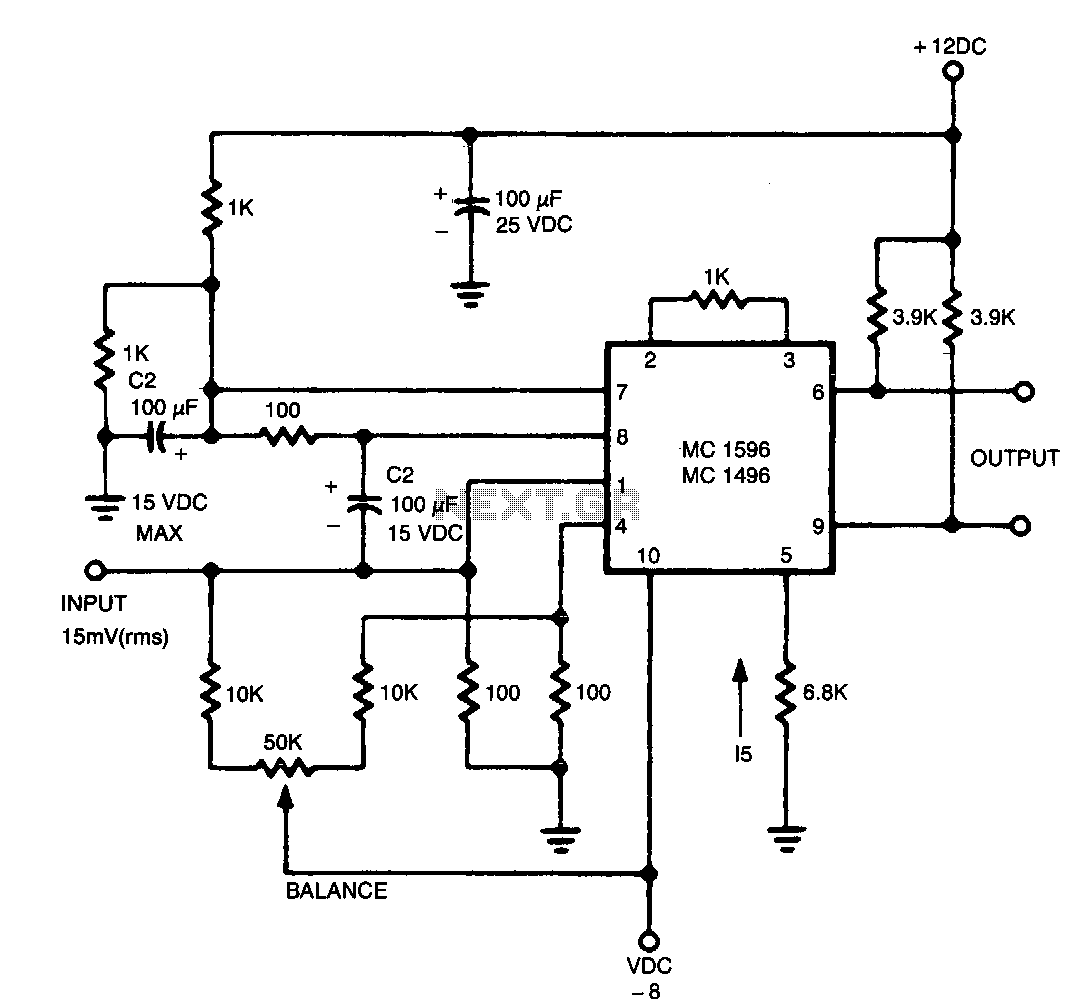
The output contains the sum component, which is twice the frequency of the input, since both input signals are of the same frequency. In a circuit design context, the described output suggests the presence of a frequency doubling mechanism, commonly...

An audio power amplifier circuit for a 3-watt stereo amplifier using the MAX 7910 IC is explained below. The audio power amplifier circuit utilizing the MAX 7910 IC is designed to deliver a maximum output power of 3 watts per...

Useful for A/B control, the IR receiver shown controls a relay from an infrared beam that has a pulsed tone-modulated signal. Q1 is the photo receptor feeding op amp IC1, tone decoder IC2, and flip-flop IC3. IC5 turns off...
This result places the oscillator within the UK FM Band, which ranges from 87.5 to 108 MHz. If L1 is equipped with an adjustable ferrite core, its inductance can be modified, allowing for fine tuning. If L1 consists of...
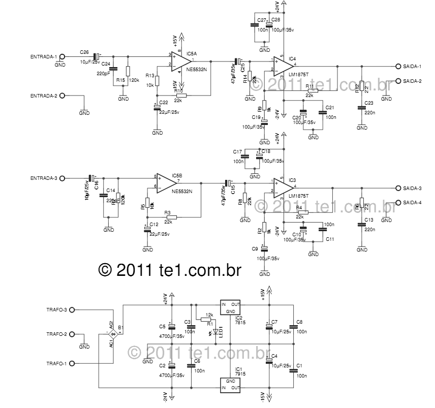
The LM1875 delivers 20 watts into a 4 or 8-ohm load on ±25V supplies. Using an 8-ohm load and ±30V supplies, over 30 watts of power may be delivered. The amplifier is designed to operate with a minimum of...
Warning: include(partials/cookie-banner.php): Failed to open stream: Permission denied in /var/www/html/nextgr/view-circuit.php on line 713
Warning: include(): Failed opening 'partials/cookie-banner.php' for inclusion (include_path='.:/usr/share/php') in /var/www/html/nextgr/view-circuit.php on line 713