
DC to DC Converter circuit
The described circuit functions as a DC to DC converter by leveraging a center-tapped transformer, which allows for the conversion of a low voltage AC input (12 VAC) into a higher voltage output suitable for various applications. The blocking oscillator configuration is essential for generating a square wave signal, which drives the transformer. This method is characterized by its simplicity and cost-effectiveness, although it comes with a trade-off in efficiency.
The operation begins with the transformer, which has a primary winding connected to the AC power source and a secondary winding that is center-tapped. This configuration provides two equal voltage outputs, which can be utilized effectively in the circuit. The blocking oscillator's feedback mechanism ensures that the transformer is driven into saturation, allowing the circuit to oscillate and produce the necessary output voltage.
Upon reaching the high-voltage side of the transformer, the voltage is further increased using a voltage tripler circuit. This tripler consists of three capacitors and diodes arranged in a specific manner to rectify and store the voltage generated. The diodes ensure that current flows in the correct direction, while the capacitors charge during the positive half-cycle of the AC waveform and discharge during the negative half-cycle, effectively multiplying the output voltage.
The end result is a high-voltage DC output that can be utilized for low-power applications, such as powering small electronic devices or charging capacitive loads. While the circuit may not be the most efficient option available, its simplicity and low component count make it a viable choice for specific scenarios where high voltage is required without the need for high power. Proper design considerations must be taken into account, including component ratings and thermal management, to ensure reliable operation within the intended application.The circuit is a DC to DC converter using a standard 12 VAC center tapped power transformer wired as a blocking oscillator. The circuit is not very efficient but will produce a high voltage usable for low power applications. The input battery voltage is raised by a factor of across the transformer and further raised by a voltage tripler consisting of three capacitors and diodes connected to the high voltage side of the transformer..
🔗 External reference
Related Circuits
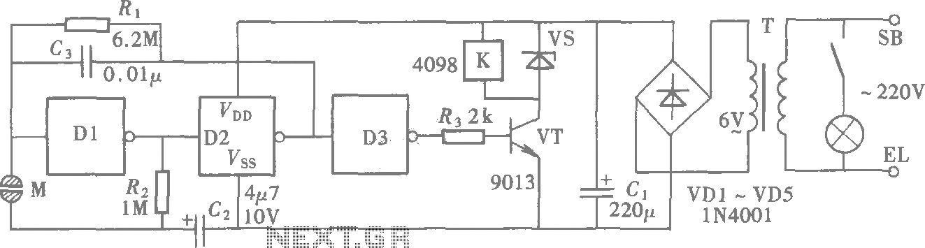
A CMOS gate exhibits high input impedance, which allows it to respond to changes in input levels due to human contact, thereby triggering the toggling of gates. The circuit utilizes this characteristic to create a touch lamp switch. The...
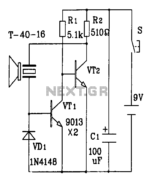
The discrete components ultrasonic transmitter circuit T/R-40-16 can emit a series of ultrasonic signals at a frequency of 40 kHz. This circuit operates at a voltage of 9V and has a current consumption of 25mA, with a control distance...
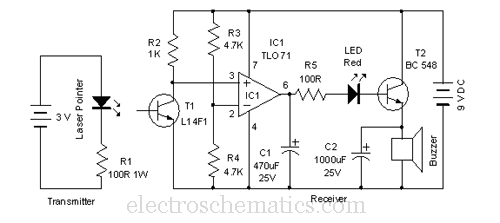
This laser door alarm operates by detecting the interruption of a laser beam. A low-cost laser pointer serves as the light source. When an individual crosses the path of the laser beam, it triggers the alarm. The laser door alarm...
This project is designed to program the 8-pin PIC12c508A and 18-pin PIC16F84 microcontroller chips to support the projects we have designed; however, it will also program a number of other 8-pin and 18-pin microcontrollers, and the full list can...
This AC drill speed controller circuit schematic allows for the control of the drilling speed of a borer or drilling machine. This project is based on the principle that... The AC drill speed controller circuit is designed to modulate the...
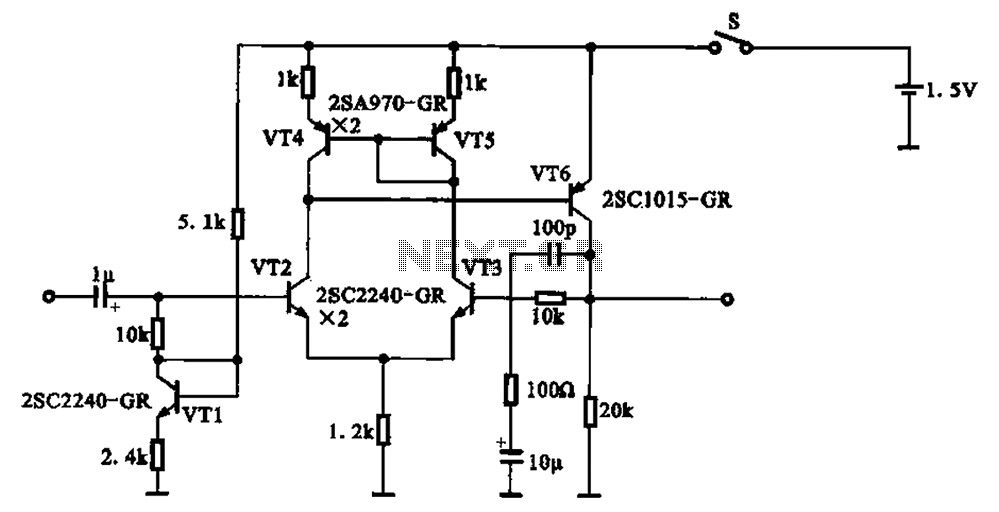
A 1.5V-powered microphone signal amplifying circuit is designed with a power supply for the microphone signal amplification. The circuit primarily consists of a differential amplifier formed by transistors VT2 and VT3. Additionally, VT6 functions as a common emitter voltage...
Warning: include(partials/cookie-banner.php): Failed to open stream: Permission denied in /var/www/html/nextgr/view-circuit.php on line 713
Warning: include(): Failed opening 'partials/cookie-banner.php' for inclusion (include_path='.:/usr/share/php') in /var/www/html/nextgr/view-circuit.php on line 713