
Direct infrared remote control switch circuit diagram composed of LS-2

The LS-2 remote control switch infrared sensor module is designed for applications requiring a reliable remote control mechanism. The module operates effectively within a voltage range of 4 to 6V DC, making it suitable for various low-voltage environments. The typical operational voltage of 5V ensures compatibility with standard electronic components and power supplies.
The control output terminals, labeled L1 and L2, are critical for interfacing with other electronic devices. These terminals output a voltage range matching the operating voltage, which allows for seamless integration into broader circuit designs. The module's ability to handle an input and output current of 50mA ensures that it can drive moderate loads, making it versatile for different applications.
The reflection capability of the LS-2 is noteworthy, as it can function effectively within a distance of 4 to 100cm when configured as a reflector. This feature is particularly beneficial in applications where proximity detection is essential. The inclusion of a current limiting resistor, ranging from 510Ω to 1kΩ, is necessary to protect the module from excessive current, ensuring longevity and reliability.
When utilized as a direct infrared remote control switch, the LS-2 can achieve a maximum operational distance of up to 8m. This extended range is advantageous for remote control applications, allowing users to operate devices from a distance without physical interaction. The basic application circuit provided with the LS-2 is designed to facilitate this functionality, ensuring that users can achieve the desired remote control distance of 5 to 8m with ease.
In summary, the LS-2 remote control switch infrared sensor module is a versatile component that offers both reflective and direct remote control capabilities, making it suitable for a wide range of electronic applications. Its electrical characteristics, including operating voltage, current specifications, and operational distances, provide a solid foundation for integration into various circuit designs.LS-2 remote control switch infrared sensor module is basically the same with the LS-18, in addition, it isused as a reflector. LS-2 Pin diagram form LS-2 internal block diagram Electrical parameters LS-2 remote control switch module operating voltage is 4 ~ 6V (DC), typical value is 5V; Operating current is 2 ~ 4mA; Control output terminal (L1, L2) output voltage is4 ~ 6V;
Input, output current is 50mA, reflection part of the power consumption is less than 1. 5mA; Ip-p reflex drive capability is greater than 50mA; When it is used as a reflection, the reflection distance is 4 ~ 100cm, corresponding external current limiting resistor is 510 © ~ lk ©; When it is used as the direct infrared remote control switch, the maximum remote control distance is up to 8m. Here is the basic application circuit of LS-2. This circuit remote control distanceis up to 5 ~ 8m 🔗 External reference
Related Circuits
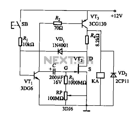
Discharge time relay circuit. The timer utilizes a field effect transistor, providing high timing accuracy and extended timing capabilities. With R3 set to 1,000,000 ohms and C at 200 microfarads, a delay time of 8 hours can be achieved....
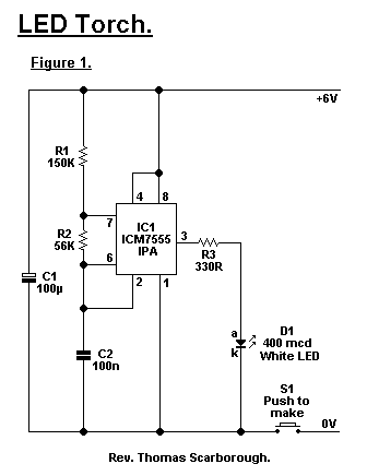
A common issue with small flashlights is the limited lifespan of both the batteries and the bulb. For example, a typical incandescent flashlight consumes approximately 2 Watts, while the LED flashlight shown in Fig. 1 consumes only 24 mW....
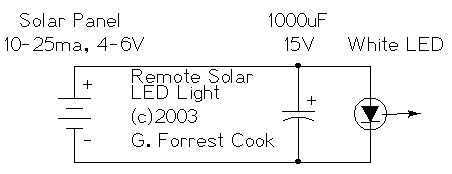
The remote solar powered LED light takes advantage of the current limited nature of solar photovoltaic cells. If light shines on the solar array, current will flow through the circuit. For a typical size of solar cell, there is...
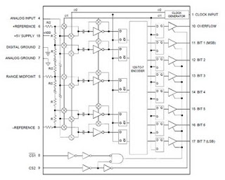
The ADC 207 is the first analog-to-digital converter to utilize Flash Converting technology based on an advanced high-speed VLSI 1.2-micron CMOS process. This innovative process enhances the unique capabilities of the ADC 207, providing excellent speed, good linearity, and...
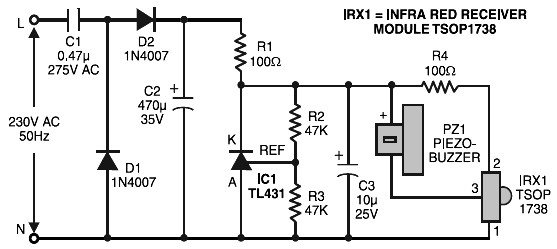
Remote control tester circuit diagram. The tester is designed around the infrared receiver module TSOP1738. The operation of the remote control is indicated by a tone from the buzzer. The circuit is sensitive and has a range of about...
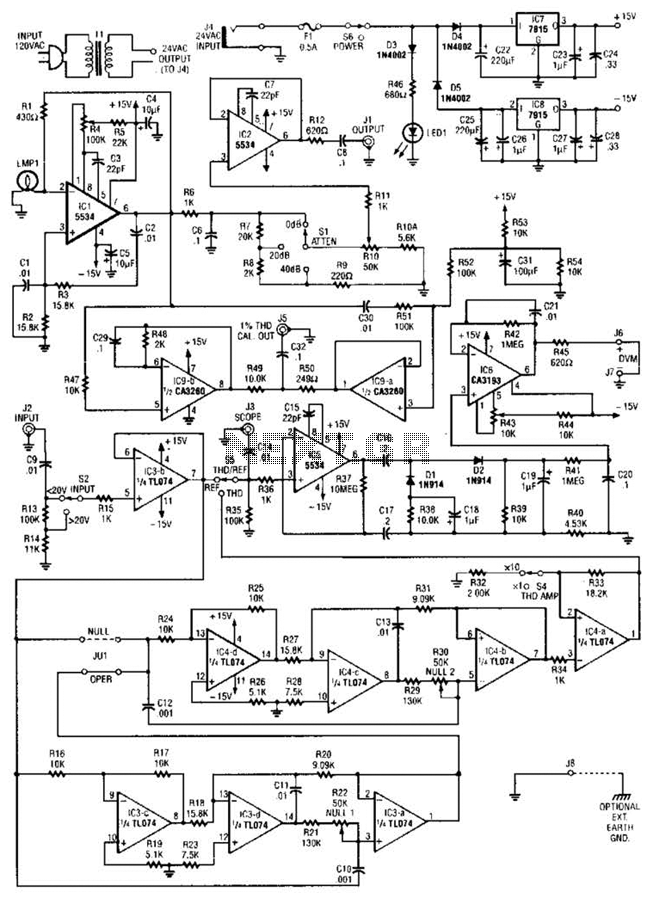
The circuit comprises a low-distortion, 1-kHz oscillator designed to measure Total Harmonic Distortion (THD) at a user-selected voltage level, suitable for voltage amplifiers or for testing amplifiers with power levels up to 600 W. It is capable of detecting...