
Audio stereo Panner

The circuit design focuses on transforming a single mono audio input into a dual output that simulates stereo sound. This is achieved through the use of a variable gain amplifier (VGA) configuration, which allows for dynamic adjustment of the audio signal levels based on an external control voltage ranging from 0 to 10 volts.
The core of the circuit consists of two operational amplifiers (op-amps) configured as summing amplifiers. The mono audio signal is fed into both op-amps, while the control voltage determines the gain applied to each channel. A potentiometer can be included in the circuit to facilitate manual adjustment of the stereo panning effect, allowing users to blend the audio signal between the left and right outputs seamlessly.
The control voltage can be generated from an analog synthesizer’s modulation sources, such as an LFO or an envelope generator, providing versatility in sound design. By adjusting the control voltage, the circuit can create various spatial effects, enhancing the listening experience.
Additionally, the circuit may include passive components such as resistors and capacitors to filter unwanted noise and stabilize the output signals. Proper grounding and shielding techniques are essential to minimize interference, ensuring high-quality audio output.
The final outputs can be connected to standard audio interfaces or mixers, making the circuit suitable for live performances or studio applications. Overall, this mono-to-stereo conversion circuit is a valuable tool for musicians and sound designers looking to expand their sonic capabilities within analog synthesizer systems.This circuit is used to convert a mono audio signal into a stereo signal that can be panned between the left and right channel by a 0-10V control signal, it is intended for analog synthesizer systems. 🔗 External reference
Related Circuits
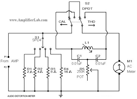
A circuit diagram of an audio distortion meter is presented here. An audio distortion meter is utilized to measure Total Harmonic Distortion (THD). The audio distortion meter is an essential tool in audio engineering, designed to quantify the level of...
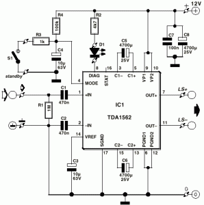
A car audio amplifier utilizing the TDA1562Q, capable of delivering 50W of audio power. The circuit diagram includes two resistors of 1 kOhm and two resistors of 4.7 kOhm. The TDA1562Q is a high-performance integrated circuit designed for car audio...
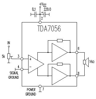
This TDA7056 power audio amplifier circuit diagram project is designed to deliver a maximum output power of 1 watt into an 8-ohm load when powered by a 6-volt supply, or a maximum output power of 3 watts into a...
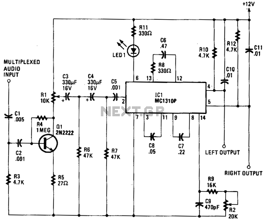
The composite input signal is amplified by transistor Q1 and is then connected to a high-pass filter consisting of capacitors C3 and C4, along with resistors R6 and R7. The filtered audio signal is subsequently sent to IC1, which...

This car audio amplifier circuit is based on the LA47536 audio amplifier integrated circuit designed by Sanyo. This audio amplifier circuit is specifically designed for car audio power amplifiers. The LA47536 car audio amplifier IC features four output channels...
The UDA1350AH is a single-chip IEC 958 audio decoder that features an integrated stereo digital-to-analog converter utilizing bitstream conversion techniques. In addition to the UDA1350AH, which is the fully-featured version packaged in a QFP44, there is also the UDA1350ATS....