
audio visual indicator for telephone circuit diagram

The circuit design is intended to provide an additional ringer that can be easily integrated into existing telephone lines without the need for external power, making it highly convenient. The use of components such as the BA8204 or ML8204 integrated circuit ensures that the design remains compact while delivering effective performance. The visual indication of the ringing signal through LED1 allows users to see when a call is incoming, adding an extra layer of functionality.
The design parameters, including the sensitivity adjustment via R3 and the frequency control through R5, C4, R4, and C3, allow for customization based on user preferences. This adaptability is crucial for achieving a sound that is not only audible but also pleasant to the user. The rectification process through the diode bridge ensures that the AC ringing signal is effectively converted to DC, which is essential for the operation of the integrated circuit.
The output from pin 8 of IC1 is designed to drive a piezo-ceramic sound generator, which is known for its efficiency and clarity in sound production. The volume control VR1 provides the user with the ability to adjust the output level, ensuring that the ringer can be heard in different environments, whether it be a quiet bedroom or a bustling living room.
Overall, this circuit represents a practical solution for enhancing telephone alert systems, ensuring that users can stay informed of incoming calls regardless of their location within a home or office setting.Many a times one needs an extra telephone ringer in an ad joining room to know if there is an incoming call. For example, if the telephone is installed in the drawing room you may need an extra ringer in the bedroom.
All that needs to be done is to connect the given circuit in parallel with the existing telephone lines using twin flexible wires. T his circuit does not require any external power source for its operation. The section comprising resistor R1 and diodes D5 and LED1 provides a visual indication of the ring. Remaining part of the circuit is the audio ringer based on IC1 (BA8204 or ML8204). This integrated circuit, specially designed for telecom application as bell sound generator, requires very few external parts. It is readily available in 8-pin mini DIP pack. Resistor R3 is used for bell sensitivity adjustment. The bell frequency is controlled by resistor R5 and capacitor C4, and the repeat frequency is controlled by resistor R4 and capacitor C3.
A little experimentation with the various values of the resistors and capacitors may be carried out to obtain desired pleasing tone. Working of the circuit is quite simple. The bell signal, approximately 75V AC, passes through capacitor C1 and resistor R2 and appears across the diode bridge comprising diodes D1 to D4.
The rectified DC output is smoothed by capacitor C2. The dual-tone ring signal is output from pin 8 of IC1 and its volume is adjusted by volume control VR1. Thereafter, it is impressed on the piezo-ceramic sound generator. Disclaimer: All the information present on this site are for personal use only. No commercial use is permitted without the prior permission from authors of this website. All content on this site is provided as is and without any guarantee on any kind, implied or otherwise.
We cannot be held responsible for any errors, omissions, or damages arising out of use of information available on this web site. The content in this site may contain COPYRIGHTED information and should not be reproduced in any way without prior permission from the authors.
🔗 External reference
Related Circuits
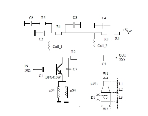
This 900 MHz amplifier circuit is constructed using the BFG480W transistor, which exhibits excellent linearity performance. As a result, the BFG480W is highly suitable for low-noise amplifiers (LNAs) that require high linearity. The 900 MHz amplifier circuit utilizing the BFG480W...
The intercom schematic provides a reliable communication line and is straightforward to construct. The circuit consists of an amplifier, two switches, and two loudspeakers. If additional stations (speakers) are desired, more switches can be incorporated into the circuit. The...
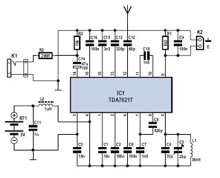
Several integrated circuits (ICs) are currently available that provide a nearly complete FM receiver solution. This project outlines a complete FM receiver circuit that offers excellent receiving and sound qualities. However, from a DIY enthusiast's perspective, the only drawback...
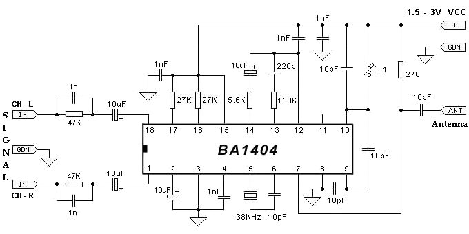
The BA1404 FM stereo modulator IC includes all the necessary components to design a simple, high-efficiency stereo transmitter circuit. It features a stereo modulator that generates composite stereo signals, an FM modulator for creating FM signals, and an RF...
The Audio Research Corporation LS22 Line Stage Preamplifier was selected for this upgrade. The Audio Research LS22 Line Stage Preamplifier is a high-performance audio component designed to enhance the quality of sound reproduction in audio systems. This preamplifier features a...

This HEXFET Audio Amplifier 65 Watts circuit diagram includes three circuit images. For a more comprehensive understanding, refer to the original post titled "HEXFET Audio Amp 65 Watts." The post not only provides circuit information but also includes a...