
Mini FM Receiver Circuit
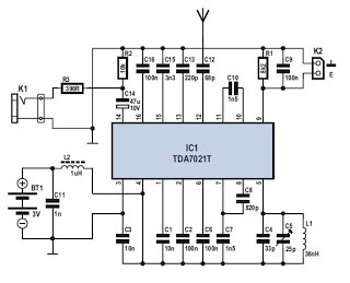
The TDA7021T IC is a versatile component designed for FM receiver applications, particularly in portable devices. Its compact nature allows for the integration of a complete receiver system within a small footprint, making it suitable for various applications where space is at a premium. The use of a frequency-locked-loop (FLL) system enhances the receiver's ability to maintain signal integrity and quality. The intermediate frequency of 76 kHz is optimal for minimizing interference and maximizing selectivity through the active RC filters, which help in filtering out unwanted signals and improving the overall sound quality.
The circuit's architecture is straightforward, with the RF signal amplification occurring at pin 12, ensuring that weak signals are adequately boosted before processing. The mixer stage effectively downconverts the signal, enabling the subsequent IF filtering stages to operate efficiently. The amplitude limiter further refines the signal, making it suitable for demodulation. The inclusion of a signal strength indicator is a valuable feature, allowing users to gauge the quality of the received signal visually, which can be particularly useful in areas with variable signal strength.
For optimal performance, the design utilizes a simple wire antenna, which can be easily constructed and connected to the PCB. The choice of SMD components not only contributes to the compact design but also enhances the reliability of the circuit by minimizing the length of the connections, which can introduce noise and interference.
In terms of audio output, while the circuit is designed for mono reception, the availability of the multiplexed signal opens up possibilities for stereo decoding. The integration of a PLL stereo decoder, such as the TDA7040T, allows for straightforward conversion of the mono output into a stereo signal, thus expanding the functionality of the receiver and enhancing the listening experience.
Overall, this FM receiver circuit is a robust solution for those seeking to create compact, high-quality FM radio applications. Its design simplicity, combined with the advanced capabilities of the TDA7021T IC, makes it an attractive option for both hobbyists and professionals in the field of electronics.There are currently several nice ICs available that contain a nearly complete receiver. This project is a complete FM receiver circuit with excellent receive and sound qualities. The only disadvantage of using this IC TDA7021T from ST-NXP Wireless, from the DIY enthusiast`s perspective, is the fact that it is only available in a 16-pin SMD package . This is a nearly complete integrated receiver circuit which has been specifically designed for portable radios and the like, requiring only a minimum of external components. As a result the final dimensions of the radio can be kept very small. The IC uses a frequency-locked-loop (FLL) system with an intermediate frequency of 76 kHz. The selectivity is obtained with the aid of active RC filters. The only calibration` adjustment in the circuit is the resonance frequency of the oscillator for the tuning.
The RF signal enters at pin 12 and is amplified first, after which it is transformed down by the mixer and passes through two IF filters. It is subsequently limited in amplitude. The IF limiter also supplies a signal for the optional signal strength indicator (via pin 9). The limited FM signal then goes to the demodulator and the correlator which decides whether the signal is tuned in properly.
The demodulated are entirely available. This is also the reason that it is not recommended to connect the audio output directly to the line input of an audio system. The complete circuit for the FM receiver is shown above. The design is virtually identical to the test circuit shown in the datasheet for the IC, because this is difficult to improve even a little without adding a lot of additional electronics.
Now we only need a few resistors and capacitors plus a coil. The tuning circuit There is also a connection (K2) for a simple signal strength meter. Via resistor R1 and decoupling capacitor C9, pin 9 supplies a DC voltage which is a measure of the received signal strength. At 170 A the output current is too small to drive an LED, but you could connect an oldfashioned` moving coil meter.
For the antenna you can use a simple wire antenna of about 75 cm long, which is soldered directly to the PCB. SMD parts are used everywhere to keep the dimensions as small as possible. Soldering these small parts requires a bit of practice however. The dimensions of this tiny PCB are only 3. 2 G— 2. 7 cm! The circuit contains no difficult coils, only the VCO requires an air-cored inductor with only 4 turns.
This receiver is a mono implementation, but at the output (as already mentioned) the entire multiplexed signal (up to 53 kHz) is available. By using a PLL stereo decoder, such as the TDA7040T, a stereo signal can be generated in a traightforward way from the output signal of the TDA7021T.
🔗 External reference
Related Circuits
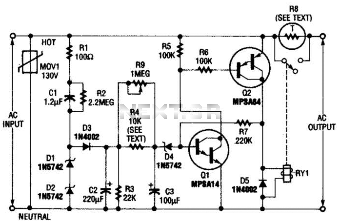
Q1 is an NPN Darlington transistor, and Q2 is a PNP Darlington transistor. MOV1 is a metal-oxide varistor, while R8 is a thermistor used for limiting inrush current. This circuit is designed to limit AC line current to a...
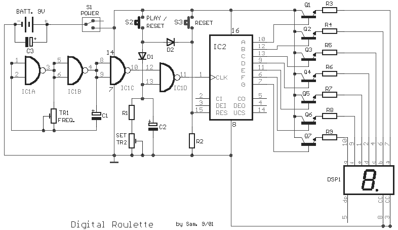
This circuit is a small digital roulette. It consists of an oscillator IC1, a counter IC2, and transistors Q1-7 that drive the common cathode display DSP1. The power supply typically comes from a 9V battery, but it can also...
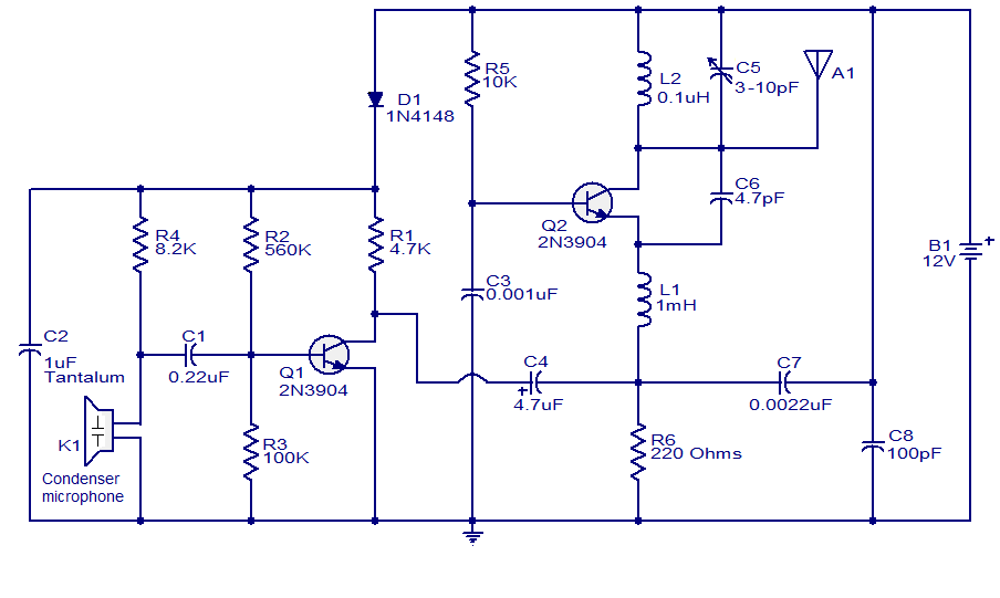
The FM transmitter circuit presented is both stable and simple. With an adaptive antenna, it can achieve a transmission range of approximately 200 meters. This transmitter was developed this year and has yielded positive results. The circuit operates using...
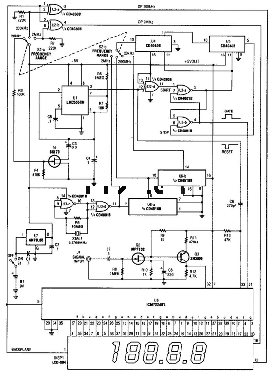
This is a schematic and block diagram of a 2-MHz frequency counter. It utilizes an LSI counter/display driver, an LCD readout, and several logic chips for timebase and timing pulse circuitry. Q2 and Q3 serve as a signal (input)...

A GdS cell serves as one leg of a bridge circuit. Potentiometer R6 in another leg establishes the trip point. Potentiometer R5 allows for hysteresis adjustment to prevent chattering or hunting of the relay. The light level must increase...
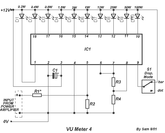
The circuit is placed parallel with the exit of power amplifier and gives the level of signal from output. Changing resistance R1 in the input circuit, we adapt the indication of power in the resistance of loudspeaker that we...