
Audio VU Meter
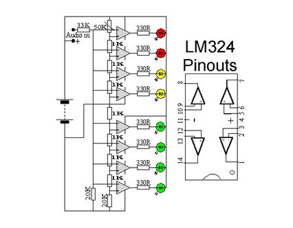
The circuit design features dual quad op-amps, specifically the LM324, which integrates four operational amplifiers in a single package, making it a cost-effective choice for audio applications. The eight LED indicators provide a visual representation of audio levels, allowing users to monitor signal strength effectively. The use of 1K resistors is instrumental in defining the threshold levels at which each LED illuminates, thereby providing a graduated display of audio amplitude.
To ensure the circuit functions optimally, careful consideration should be given to the resistor values. While 1K resistors are standard, experimenting with higher values can yield different activation thresholds, although caution must be exercised to avoid values that prevent LED activation altogether. The circuit's expandability allows for additional op-amps to be incorporated, which can enhance the number of LED indicators or refine the circuit's responsiveness to audio signals.
The inclusion of a 33K resistor serves to limit the input signal level, preventing distortion and ensuring accurate level readings. If a 33K resistor is unavailable, substituting with a resistor of a similar value is acceptable, but testing is recommended to confirm proper function. Prototyping on a breadboard is essential for evaluating circuit performance and making necessary adjustments before committing to a PCB design.
The circuit is designed to accept line-level inputs, commonly found in audio equipment, which simplifies integration with existing systems. However, modifications can be made to accommodate speaker-level inputs, broadening its application scope. The connection of the audio positive to the main positive rail ensures that the circuit has a stable power supply, while the audio signal input is processed through the op-amps to drive the LED indicators. The 50K potentiometer adds versatility, allowing users to fine-tune the sensitivity of the audio level meter, adapting it to different audio sources and environments.This circuit uses two quad op-amps to form an eight LED audio level meter. The op-amp used in this particular circuit is the LM324. It is a popular IC and should be available from many parts stores. The 1K resistors in the circuit are essential so that the LED`s turn on at different audio levels. There is no reason why you can`t change these resis tors, although anything above 5K may cause some of the LED`s to never switch on. This circuit is easily expandable with more op-amps, and is not limited to use with the LM324. Pretty much any op-amp will work as long as you look up the pinouts and make sure everything is properly connected. The 33K resistor on the schematic is to keep the signal input to the circuit at a low level. It is unlikely you will find a 33K resistor, so the closest you can get should do. The value of this resistor may need to be changed, so it is best you breadboard this circuit before actually constructing it on PCB.
The circuit in it`s current form will accept line level inputs from sources such as the aux out on a Hi-Fi, all though could be easily modified to accept speaker inputs. The audio + is connected to the main positive rail, while the audio is used for signal input. The 50k pot can be used to vary the sensitivity of the circuit. 🔗 External reference
Related Circuits
The three stages commonly found in audio amplifiers and operational amplifiers are clearly visible. However, actual audio designs often feature modifications and enhancements in key areas. This overview highlights design improvements in audio amplifiers, focusing on each of the...
The circuit utilized was primarily designed for audio mixing, featuring inputs from both a triangular wave generator and a noise generator. These signals are processed through an audio mixer to create the final output wave. This audio mixing circuit integrates...
The ultrasonic signal received by the reception sensor is amplified by a factor of 1000 (60 dB) using a two-stage operational amplifier. The first stage provides a gain of 100 (40 dB), while the second stage offers a gain...
A digital micro-ohm meter is essential for assessing the condition of shunts used in the Electrochemical Analysis & Diagnostics Laboratory (EADL) at Argonne National Laboratories. A shunt is essentially a small resistor utilized for current measurement. The micro-ohmmeter will...
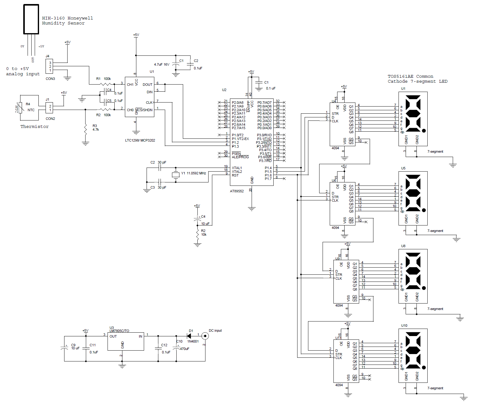
This circuit features a microcontroller AT89S52 paired with a 12-bit ADC LTC1298. The programs are written in C and include digital filtering, interfacing with a 0.5-inch 7-segment LED display. The thermometer provides a sensitivity of 0.1°C. The hardware block...
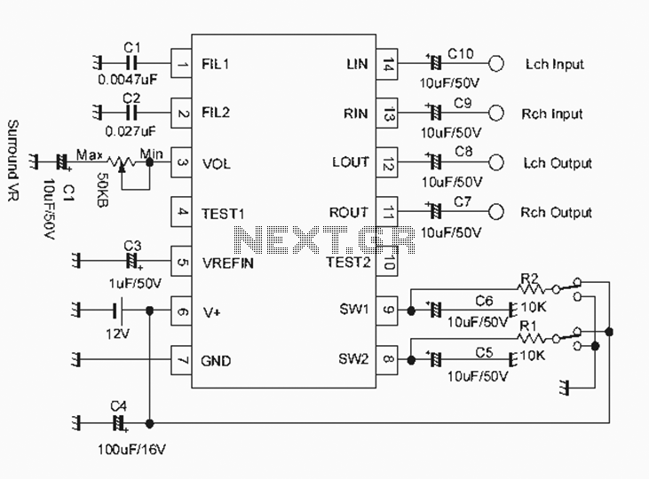
The NJM2701 3D surround sound audio processor integrated circuit can be designed into a very simple 3D surround sound system. The NJM2701 reproduces 3D surround sound using only two speakers and is suitable for various audio applications, including micro-components,...