
25W Mosfet audio amplifier
The described circuit functions as an audio amplifier capable of interfacing directly with various audio sources such as CD players, tuners, and tape recorders. The design incorporates a dual gang 10K logarithmic potentiometer, which allows for stereo volume control, and a switch to select between different audio sources. This flexibility is essential for users who require a versatile audio setup.
The amplifier is specified to deliver an output power exceeding 25 Watts RMS into an 8 Ohm load at a frequency of 1 kHz. This power output is significant for driving typical speakers in home audio applications. The input sensitivity of the amplifier is noted to be 200 mV for achieving the 25 Watt output, indicating that it can effectively amplify low-level audio signals without requiring excessive input voltage.
The frequency response of the amplifier is specified as 30 Hz to 20 kHz with a tolerance of -1 dB. This range covers the full audible spectrum, making the amplifier suitable for a wide variety of audio content, from deep bass to high treble frequencies.
Thermal management is addressed in the design, with specific components requiring heatsinks to dissipate heat generated during operation. Transistors Q6 and Q7 are to be equipped with small U-shaped heatsinks, while Q8 and Q9 require larger heatsinks for effective thermal regulation. Proper thermal management is crucial to maintain performance and reliability, preventing overheating that could lead to component failure.
The quiescent current, which is the idle current flowing through the amplifier when no audio signal is present, is adjusted via resistor R11. It is recommended to set this current to 100 mA, which can be accurately measured using an Avo-meter placed in series with the drain of Q8. This adjustment is vital for ensuring optimal performance and minimizing distortion during operation.
Lastly, the design emphasizes the importance of correct grounding practices to eliminate noise and interference, which can adversely affect audio quality. Proper grounding techniques will ensure a clean and clear audio output, free from unwanted hum or noise artifacts.Can be directly connected to CD players, tuners and tape recorders. Simply add a 10K Log potentiometer (dual gang for stereo) and a switch to cope with the various sources you need. Output power: well in excess of 25Watt RMS @ 8 Ohm (1KHz sinewave) Sensitivity: 200mV input for 25W output Frequency response: 30Hz to 20KHz -1dB
Q6 & Q7 must have a small U-shaped heatsink. Q8 & Q9 must be mounted on heatsink. Adjust R11 to set quiescent current at 100mA (best measured with an Avo-meter in series with Q8 Drain) with no input signal. A correct grounding is very important to elim 🔗 External reference
Related Circuits
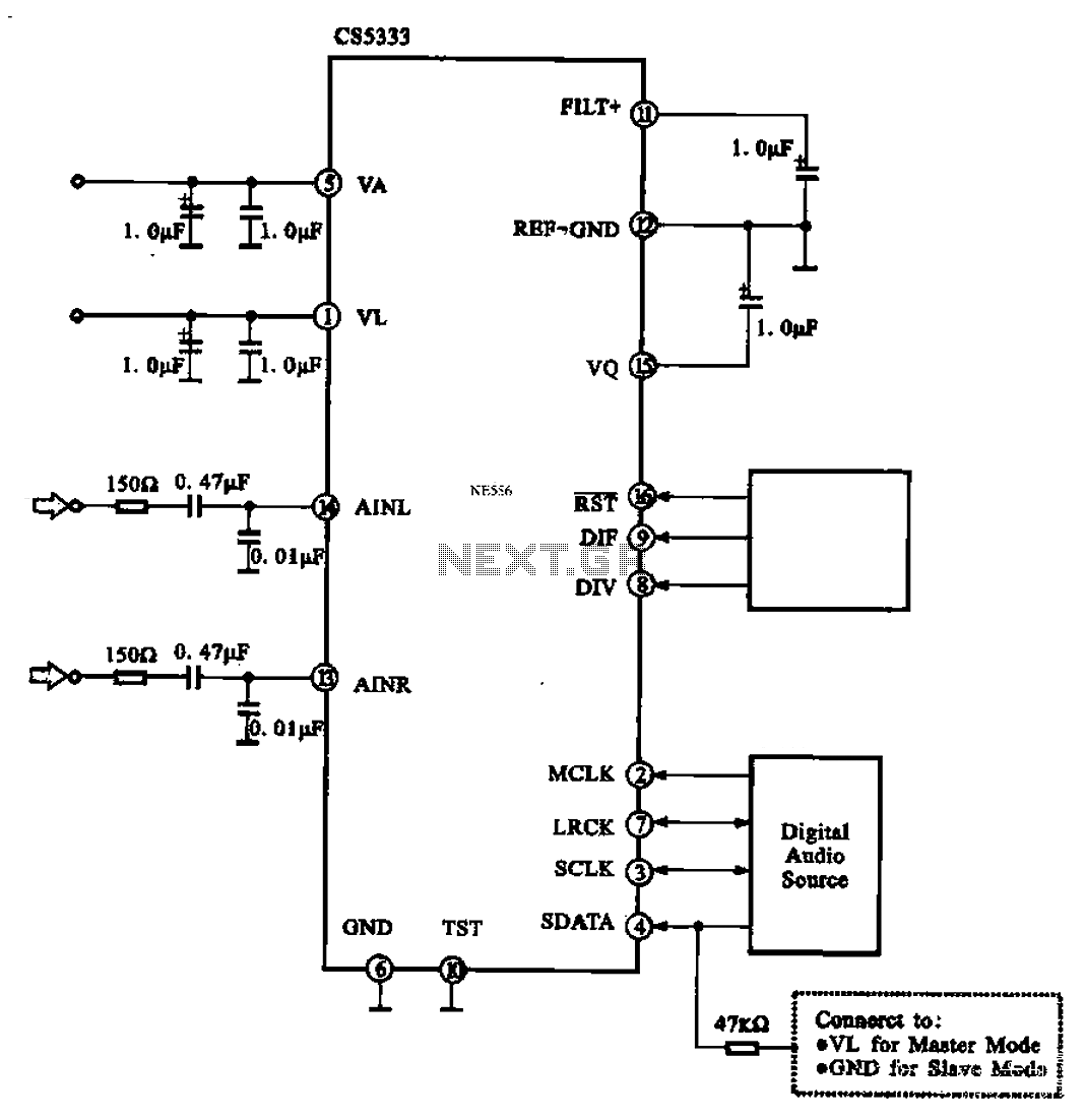
Audio A/D converter circuit configuration using the CS5333 chip, which is a high-performance 24-bit, 96 kHz stereo A/D converter commonly used in digital products. This circuit converts one or more audio signals into a digital signal for processing and...
This circuit diagram represents an ECM Mic Preamplifier. It is a microphone amplifier compatible with Electret Condenser Microphones (ECM). The preamplifier exhibits an excellent dynamic range, capable of handling audio levels from a whisper to a scream; however, caution...
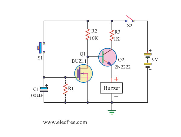
This is an On After Delay Circuit that utilizes a MOSFET for delay, which is simpler than using a transistor. The operation of the circuit is triggered when switch S1 is pressed. The On After Delay Circuit is designed to...
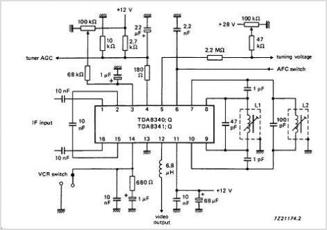
The TDA9813T is an integrated circuit designed for processing vision intermediate frequency (IF) signals and dual frequency modulation (FM) demodulation of sound. It operates with a single reference QSS-IF in television (TV) and video cassette recorder (VCR) applications, specifically...
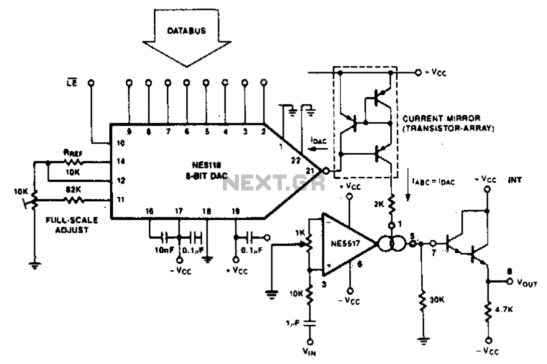
The purpose of the following application is to demonstrate how the NE5517 operates in conjunction with a DAC. The application utilizes the NE5118, an 8-bit DAC with current output, featuring an input register that makes this device fully micro-compatible....
Circuit stereo TDA2822 audio power amplifier circuit schematics. In this series, the TDA2822M IC is utilized as the primary amplifier. Additionally, alternatives such as KA2209 and NJM2073 can also be employed. The TDA2822 audio power amplifier circuit is designed to...