
ecm mic preamplifier
The ECM Mic Preamplifier circuit is designed to provide high-quality audio amplification while maintaining low noise levels. The use of low-noise transistors such as the BC549C or BC109C is crucial for achieving the desired performance characteristics. The circuit's self-stabilizing feature is essential for ensuring consistent operation across varying conditions, particularly in environments where temperature fluctuations may occur.
In the first stage, the Q1 transistor is configured to operate at low collector currents, which is vital for enhancing the signal-to-noise ratio. The bypass capacitor (100μF) allows AC signals to pass while blocking DC, improving the amplifier's response to audio frequencies. The choice of a 1k resistor for current limiting is a critical design element, as it protects the microphone and ensures optimal performance. The recommendation to increase this resistor to 2.2k when using higher supply voltages is a precautionary measure to prevent excessive current flow, which could damage the microphone.
The second stage, utilizing Q2, is designed for minimal phase shift, which is advantageous for preserving audio fidelity across a wide frequency range. This direct coupling method enhances the amplifier's ability to reproduce sound accurately, making it suitable for professional audio applications. The feedback mechanism from Q2 to Q1 not only stabilizes the operating point but also contributes to the overall temperature stability of the circuit, ensuring reliable performance over time.
Overall, the ECM Mic Preamplifier circuit is an effective solution for amplifying audio signals with a high degree of fidelity and low noise, making it suitable for various applications in audio engineering and recording. Its design considerations, including component selection and circuit configuration, reflect a thorough understanding of the principles of audio amplification and signal integrity.This circuit is a circuit diagram of ECM Mic Preamplifier. A microphone amplifier that can be used with either Electret Condenser Microphone (ECM). Preamplifier has a dynamic range very well and can handle anything from a whisper to a scream, but must be careful to ensure that the equipment that aids the amplifier or tape deck is not excessive. In the original series, I used BC650C ultra low voice device. This transistor is now difficult to find but BC549C or BC109C a good substitute. Circuit is to stabilize itself and will set the still point at roughly half the supply voltage to the emitter of Q2. The following is a schematic drawing: In this circuit diagram, 1k resistor limits the current to the mic.
This resistor should be increased to 2k2 if the supply voltage above 12 Volts DC is used and not needed if the Mic insert is dynamic. The first stage built around Q1 amplifier is run at very low collector currents. These factors contribute to a very high overall signal to noise ratio and low overall sound output. The Q1 emitter resistor is separated by 100u bring this up to stage. Voice responses measured from the amplifier in the whole load is shown below 10k. Please note that this plot was made by inserting mic signal is replaced by a generator. The second phase, built around Q2 is coupled directly, this minimizes the effect of phase shift (introduced by the capacitive and inductive coupling method) and achieve a flat output response from 20Hz to over 100kHz.
Frequency response is measured across the 10k load resistor. Q2 emitter voltage is also eaten back to basics Q1 through resistive coupling. This is also biased againt ensure temperature stabilization effect. Q2 operates in emitter follower mode, voltage gain of this stage is less than unity, however, the overall voltage gain of the Preamplifier is about 100x or 20db as shown in the plot above the sign. Very low output impedance and is suitable for driving the cable distances up to 50 meters. 🔗 External reference
Related Circuits
A lot of friends asked me to draw a more shrunk circuit 2-ch mixer, which will contain also, operation CROSSFADER. The circuits can be modified and added also other channels, repeating basic that I give. It can be added...
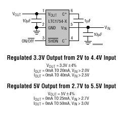
The LTC1754 is a micropower charge pump DC/DC converter that produces a regulated output. The input voltage range is 2V to 4.4V for a 3.3V output and 2.7V to 5.5V for a 5V output. Its extremely low operating current...
The TRW-24G connector pins are quite small, approximately 1mm apart. To address this issue, an adaptor PCB has been ordered to convert the small connector of the RF module to a standard pin connector. The pin arrangement of the...
The next stage operates in conjunction with the first stage and is fully complementary. A cascode circuit is included to enhance the linearity of the amplifiers. This cascode circuit requires a constant reference voltage for biasing to activate the...
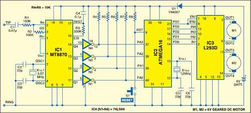
This instructable is categorized under 13 - 18 in the National Robotics Week Robot Contest. The National Robotics Week Robot Contest encourages innovation and creativity in robotics among participants aged 13 to 18. This category represents a significant opportunity for...
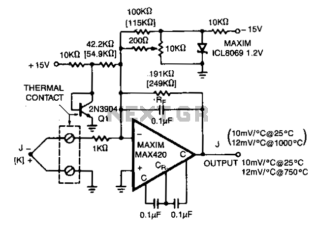
The MAX420 is operated at a gain of 191 to convert the 52 µV/°C output of the type J thermocouple to a 10 mV/°C signal. The -2.2 mV/°C temperature coefficient of the 2N3904 is added into the summing junction...