
LM4561 LM4562 consisting of 170W power amplifier circuit
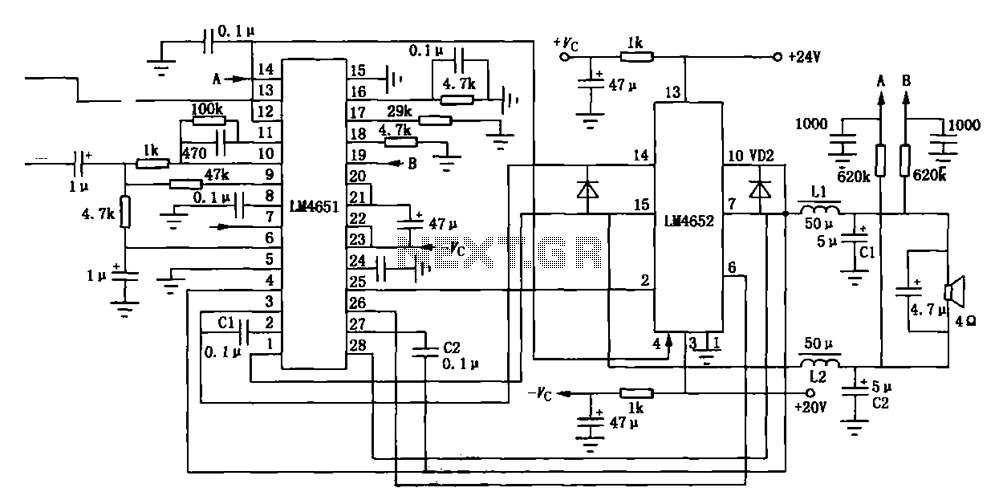
The 170W output amplifier circuit is engineered to drive speakers with a nominal impedance of 4 ohms, making it suitable for high-power audio applications. The LM4651 class D amplifier utilizes pulse-width modulation (PWM) to efficiently convert the input audio signal into a high-power output while minimizing heat generation.
The 28-pin DIP package of the LM4651 facilitates easy integration into various circuit designs. It includes essential features such as over-temperature protection, short-circuit protection, and a built-in low-pass filter to smooth the PWM output, ensuring high fidelity in audio reproduction.
The internal equivalent circuit of the LM4651, as shown in Figure (c), provides insight into the amplifier's operational characteristics, including the arrangement of transistors, feedback loops, and the power supply configuration. The efficient switching mechanism of the class D architecture allows for high output power levels while maintaining low distortion, making it ideal for modern audio amplification needs.
Further analysis of the circuit design reveals the importance of component selection, including the choice of inductors and capacitors, which directly impacts the amplifier's performance and efficiency. Proper layout considerations in PCB design are also crucial to minimize parasitic inductances and capacitances, ensuring optimal signal integrity and thermal management within the amplifier. Overall, this amplifier circuit exemplifies the advancements in audio amplification technology, combining high power, efficiency, and compact design.Figure (a) shows the output amplifier circuit 170W at 4 loads; LM4651 is a former circuit class D amplifier, a 28-pin DIP package, the internal equivalent circuit is shown in ( c),
Related Circuits
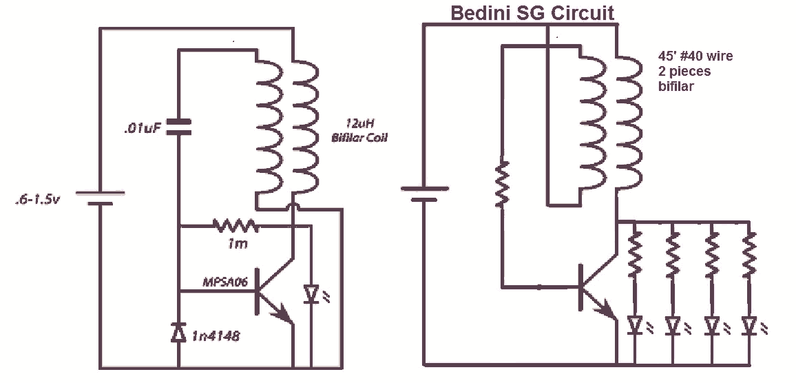
It would be beneficial to obtain schematics of the Joule Thief and Bedini oscillator circuit connections. This is an area that has not been previously explored. The schematic on the left was sourced from the Energetic Forum, while the...
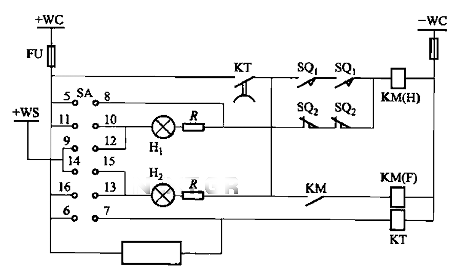
The BT9404 is a de-excitation type switch utilized with CJ4-S contactors and JT3-21/3-type electromagnetic relays. The control circuit is depicted in Figure 7-55. The KM contactors used are CJ4-S, while the time relay is the JT3-21/3. The SA component...
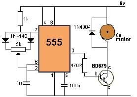
This project utilizes a 555 timer to control the speed of a 6-volt DC motor. Speed adjustment is achieved by rotating a 50 kΩ potentiometer either to the left or right. The circuit employs a 555 timer configured in astable...
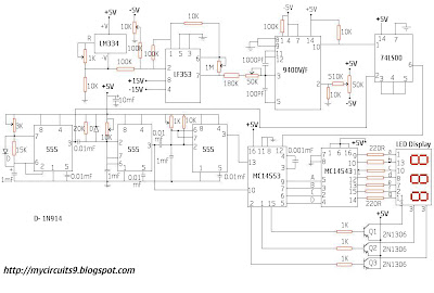
This circuit consists of a temperature sensor, amplifier, voltage-to-frequency (V/F) converter, a three-digit binary coded decimal (BCD) counter, a time base, and seven-segment LED displays. In addition to the 9400 V/F converter, other integrated circuits (ICs) required for this...
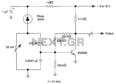
The circuit utilizes a tuned circuit for frequency selection, designed to operate at approximately 51 kHz. The 2N3565 transistor amplifies the output generated by the tuned circuit. The described circuit operates on the principle of resonance, where the tuned circuit...
The circuit presented is a 20W audio amplifier utilizing the LM1875 integrated circuit (IC). The LM1875 is a high-quality, low-distortion audio amplifier IC rated for 20 watts, available in a TO-220 package. This IC includes several built-in features such...