
Auto Baud Rate with PIC18F2455

The described circuit utilizes the Enhanced Universal Asynchronous Receiver-Transmitter (EUSART) module found in newer PIC microcontrollers, specifically the PIC18F2455. The EUSART module is equipped with an automatic baud rate detection feature that enhances communication efficiency in serial communications. The operation begins with the microcontroller waiting for a specific character, "U" (0x55), which is sent over the RX pin. This character triggers the auto baud rate detection functionality, which is enabled by setting the ABDEN bit in the control register.
Upon receiving the character, the microcontroller uses the BRG clock as a reference to determine the baud rate by counting the rising edges on the RX pin. This process involves calculating the values for SPBRG and SPBRGH registers, which are essential for configuring the baud rate. Once the baud rate is successfully set, the RCIF (Receive Interrupt Flag) is activated, indicating that the baud rate configuration has been completed. It is important to note that the data in the receive register is not meaningful in this context and should be discarded.
The implementation of this functionality is further demonstrated through a circuit similar to a UART test setup. The attached project file contains code that initializes the microcontroller and configures the auto baud rate detection. The UARTReadByte() function is utilized to read and subsequently discard the byte received after the baud rate has been configured. This is critical to ensure that the system does not process irrelevant data.
In conjunction with the microcontroller, an LCD display is employed to provide visual feedback. After the successful programming of the microcontroller, the LCD will reflect the system's status, indicating that it is waiting for the character "U" to initiate the baud rate setting process. This comprehensive setup illustrates the capability of the EUSART module to dynamically adapt to varying baud rates, thus enhancing the robustness and flexibility of serial communication in embedded systems.Most of the newer PIC come with the EUSART module which have the function for auto baud rate detection. The features allow a person to set the baud rate at runtime by sending the character "U" or 0x55 to the PIC.
With ABDEN (auto baud rate enable) bit set and using BRG clock as a reference, each rising edge occurring on the RX pin is taken as a reference to calculate the SPBRG and SPBRGH value. After the Baud rate is set, the RCIF flag will be set. The receive register must be discarded as it doesn't contain meaningful data. The Image (PIC18F2455 datasheet, page 252) below shows the timing diagram for auto baud rate setup. A circuit based similar to the UART test is used to demonstrate the capability of auto baud rate generation.Using the code in the project file attached, It will 1st wait for a character "U" to be send over for baud rate calculation. Auto baud is enable using the 3 lines of code below. The UARTReadByte() will read and discard the byte after a successful configuration of baud rate. The LCD display will be the same as the image below after a successful program of the microcontroller.
It is currently waiting for the character U to set the baud rate. 🔗 External reference
Related Circuits
The automobile interior lights fader circuit diagram is designed to gradually brighten and dim the interior lights of older vehicles. This circuit utilizes the LM324 low-power operational amplifier as its core component. The automobile interior lights fader circuit is an...
The previous article discussed the circuit diagram of an HHO gas generator, and this section explores its practical implementation. The circuit diagram is explained in detail. The HHO gas generator circuit is designed to produce hydrogen and oxygen gases through...
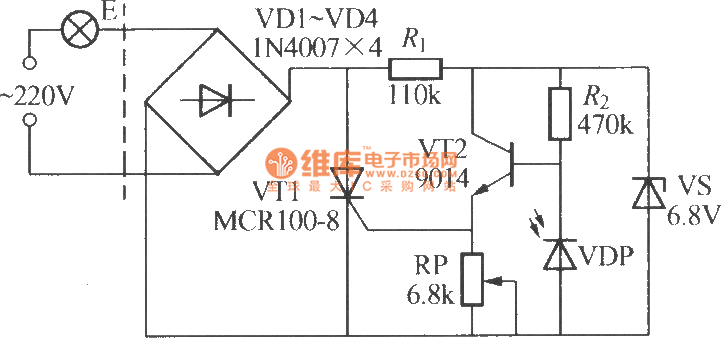
The VDP is a photodiode that exhibits low resistance during the day, approximately 1 kΩ. As a result, transistor VT2 remains off, which keeps thyristor VT1 in the off-state due to the absence of trigger current at the gate,...
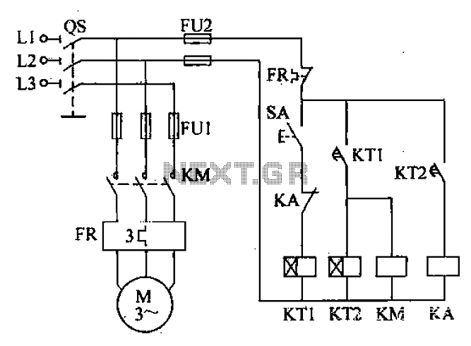
After the power switch is activated, the motor does not start immediately but instead has a specified delay period. This setup allows the machine to perform automatic intermittent lubrication control. The circuit for the motor boot delay and intermittent...

This Project Automatic Room Light Controller with Visitor Counter using Microcontroller is a reliable circuit that takes over the task of controlling the room lights as well as counting the number of persons/visitors in the room very accurately. When...
It is a miniature 10/100-MbBit Ethernet module that includes an integrated microcontroller. The price is less than $60. With its minimal dimensions of 1.38 in. x 2.16 in. (34.5 mm x 54 mm), the communications module can be used...