
Simple light-operated street lamp circuit diagram(3)
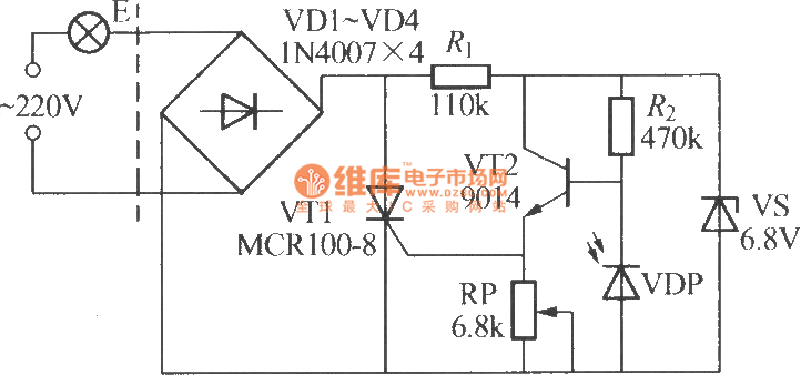
The circuit involves a photodiode (VDP) functioning as a light sensor, controlling the state of a transistor (VT2) and a thyristor (VT1). During daylight, the low resistance of the photodiode results in VT2 being non-conductive, which in turn ensures that VT1 remains off since there is no gate current to trigger it. Consequently, the emitter (E) does not receive power, thus remaining inactive.
In contrast, during nighttime, the photodiode's resistance increases significantly due to the absence of light, reaching approximately 100 kΩ. This high resistance activates VT2, allowing it to conduct. The activation of VT2 subsequently provides the necessary trigger current to the gate of thyristor VT1, turning it on. When VT1 is triggered, it allows current to flow to the emitter (E), resulting in its activation.
This configuration can be utilized in various applications, such as automatic lighting systems, where the circuit responds to ambient light levels. The transition between day and night conditions is critical for the operation of this circuit, ensuring that the emitter is only powered in low-light conditions. Proper selection of components, such as the photodiode, transistors, and thyristor, is essential to achieve the desired response times and sensitivity to light changes. The circuit may also include additional elements such as resistors for biasing and capacitors for filtering, which can enhance performance and stability.VDP is the photodiode and it has low resistance in the day, and resistance ? 1k?, then transistor VT2 is turned off, then thyristor VT1 is in the off-state as the gate has no trigger current, and E can not be lit. In the night, VL shows a high resistance as no light exposure, and the resistance ? 100k?, then VT2 is turned on, and the emitter can output pos.. 🔗 External reference
Related Circuits
The LM1875 is a monolithic audio amplifier that provides very low distortion and high-quality performance for audio amplifier projects. The LM1875 delivers 20 watts into loads of 4 Ohms or 8 Ohms. The LM1875 audio amplifier is designed for applications...
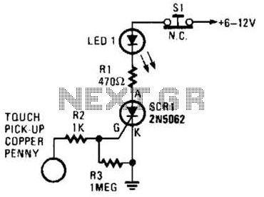
When the touch-on contacts are bridged, pin 6 of U1 goes low, which forces its output (the set output) at pin 4 to go high. That high divides along two paths; in one path, the output is applied to...
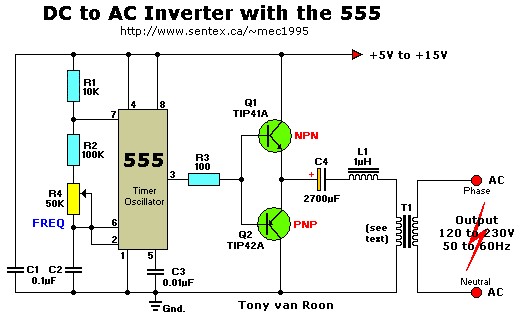
This simple 12V DC to 220V AC inverter circuit generates an AC output at line frequency and voltage. The 555 timer is configured as a low-frequency oscillator, adjustable over the frequency range of 50 to 60 Hz via the...
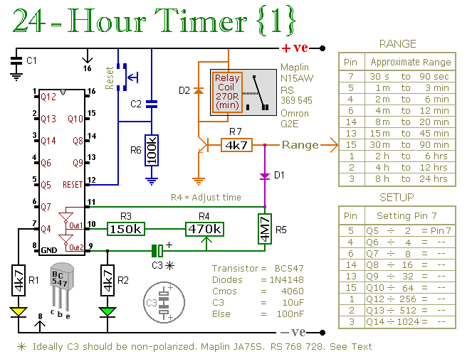
A pair of multi-range timers that provide timing periods extending up to 24 hours and beyond. Both timers are fundamentally identical, with the primary distinction being their relay behavior upon the completion of the timing cycle. Version 1 activates...
This compact amplifier is built around the TDA2003 integrated circuit, which can deliver 4W RMS at a 4-ohm load. The TDA2003 offers enhanced performance while maintaining the same pin configuration as the TDA2002. It retains the advantageous features of...
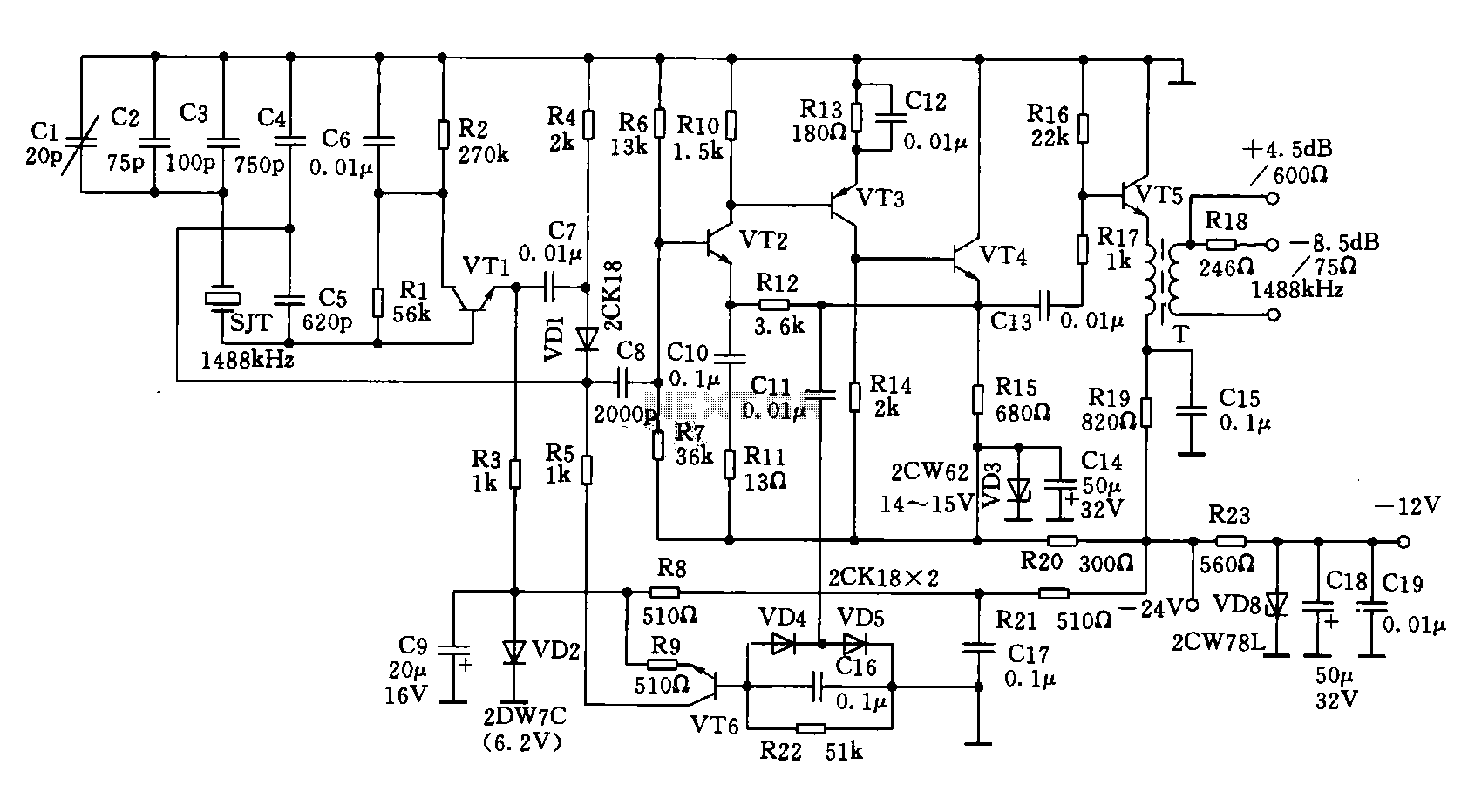
A 1488 kHz master oscillator quartz crystal resonator is utilized for frequency stabilization. The output from the frequency divider provides three different square wave signal outputs at 4 kHz, 12 kHz, and 124 kHz. The circuit includes transistors VT1,...
Warning: include(partials/cookie-banner.php): Failed to open stream: Permission denied in /var/www/html/nextgr/view-circuit.php on line 713
Warning: include(): Failed opening 'partials/cookie-banner.php' for inclusion (include_path='.:/usr/share/php') in /var/www/html/nextgr/view-circuit.php on line 713