
Auto boat or barricade flasher
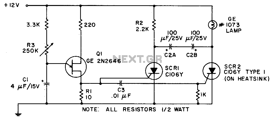
The incandescent lamp flasher circuit is designed to provide a variable flashing output using a silicon-controlled rectifier (SCR), specifically the C106 model. This component is essential for managing the high inrush currents that occur when the lamp is initially energized. The C106 SCR operates by allowing current to flow through it when triggered, and it remains conducting until the current drops below a certain threshold, making it ideal for applications requiring robust switching capabilities.
The circuit configuration typically includes a resistive-capacitive (RC) timing network that determines the flash rate of the lamp. The potentiometer R3 plays a crucial role in this network, as it allows for the adjustment of the time constant of the circuit. By varying the resistance, the charge and discharge times of the capacitor can be altered, directly affecting the frequency of the flashing output.
In practice, the flash rate adjustment can be observed through the lamp's brightness and the frequency of the on-off cycling. The range of 36 to 160 flashes per minute provides versatility for different applications, such as decorative lighting or signaling devices. Additional components in the circuit may include diodes for flyback protection, resistors for current limiting, and capacitors for filtering to ensure stable operation.
Overall, this incandescent lamp flasher circuit exemplifies a practical application of SCR technology in controlling lighting effects, with adjustable parameters to suit specific user requirements.Because of its ability to withstand the heavy inrush currents, this incandescent lamp flasher uses the C106 SCR With the components shown, the flash rate is adjustable by potentiometer R3 within the range of 36 flashes per minute to 160 flashes per minute. 🔗 External reference
Related Circuits
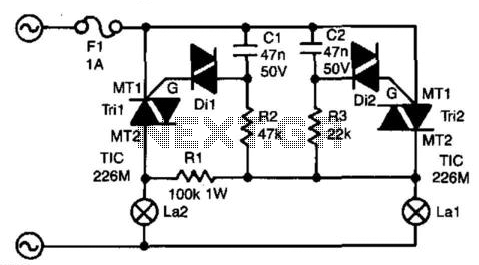
The circuit presented here ensures that if bulb La1 fails, bulb La2 will take over its function. In series with La1 is triac Tri2. Resistor R3 and capacitor C2 form a delay network. When the voltage across C2 exceeds...

This is a simple circuit that can be used as a sequential signal light in automobiles. The circuit is based on two integrated circuits (ICs): a TS 555 CN CMOS timer IC and a CD4017 decade counter IC. The...

The circuit diagram for the automatic headlights turn-off circuit is presented here. This circuit can be installed in a car. The automatic headlights turn-off circuit is designed to enhance vehicle safety and convenience by ensuring that the headlights are automatically...

Many times exists the need recording some conversations from a telephone line and this it's relatively easy. If we want however to have the possibility recording from two telephone lines simultaneously in a tape recorder, we needed a circuit...

This is essentially a flasher circuit modified to control a bulb instead of an LED. It utilizes a 555 timer integrated circuit functioning as an astable multivibrator. The flashing rate can be adjusted from very fast to a maximum...
The micropower circuit automatically provides shutdown, power-up, and low-battery lockout functions without requiring software or operator control. The micropower circuit is designed to manage power efficiently in battery-operated devices, ensuring optimal functionality while conserving energy. The shutdown feature is activated...
Warning: include(partials/cookie-banner.php): Failed to open stream: Permission denied in /var/www/html/nextgr/view-circuit.php on line 713
Warning: include(): Failed opening 'partials/cookie-banner.php' for inclusion (include_path='.:/usr/share/php') in /var/www/html/nextgr/view-circuit.php on line 713