
"Automatic" Light Bulb Changer
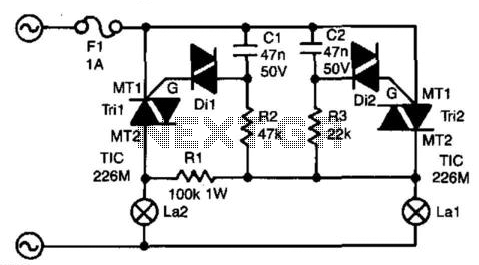
This circuit operates as a failover mechanism for lighting systems, ensuring continuous illumination even if one bulb fails. The triac Tri2 is essential for controlling the operation of bulb La1, while the resistor R3 and capacitor C2 create a delay that allows for a brief moment of voltage buildup before activating the diac D2. This delay is crucial for preventing simultaneous activation of both bulbs, which could lead to flickering or inconsistent brightness levels.
When La1 fails, the circuit is designed to sense this condition through the voltage drop across the RC networks. The initial activation of Tri2 allows for a momentary current flow, but due to the holding current characteristics of Tri2, it will cease to conduct shortly after. This design ensures that Tri1 remains inactive until the system stabilizes, allowing capacitor C1 to charge sufficiently. Once charged, Tri1 activates, illuminating La2.
The time constants for the RC networks are critical in determining the operational characteristics of the bulbs. By adjusting the values of R2/C1 and R3/C2, the designer can fine-tune the delay and brightness levels of La1 and La2, ensuring that La2 provides adequate lighting without overwhelming brightness compared to La1.
The circuit is rated for robust performance, with the capability to handle significant power levels, especially when equipped with heatsinks. This feature makes it versatile for various lighting applications, though care should be taken to use appropriate wattage bulbs to prevent flickering. The selection of triacs is also important, as they must meet the voltage and current handling requirements to ensure reliable operation over time. This design exemplifies a practical approach to redundancy in lighting systems, enhancing reliability and user experience. The circuit presented here guarantees that if bulb Lai "gives up the ghost," bulb La2 will take over its tas k. In series with Lai is triac Tri2. Resistor R3 and C2 form a delay network. As soon as the voltage across C2 rises above about 30 V, diac (gateless triac) D2 is switched on, which causes Tri2 to conduct so that Lai lights. The control circuit of La2 is parallel to that of Lai, but because R2/C1 has twice the delay of R3/C2, Tril will not be triggered when Tri2 conducts; CI discharges so that Tril cannot be triggered.
When, however, Lai is open-circuited, a voltage is across both RC networks via La2 and Rl. Again, Tri2 will be triggered first, but because the current is smaller than its holding current, it will cease to conduct almost immediately. Capacitor CI will then continue to charge and after a little while Tril is switched on. Because the time constant for La2 is somewhat longer than that for Lai, La2 will always be slightly less bright than Lai.
It is, of course, possible to give La2 a slightly higher wattage than Lai to ensure equal brightness. Without heatsinks, the triacs can handle up to 100 W each; with heatsinks, powers of up to 1000 W can be accommodated.
It is not recommended to use bulbs with a wattage below 25 W, because these can flicker. The triacs can be any type that can handle at least 400 V at no less than 5 A. The M types used in the prototype can handle 600 V at 5A. 🔗 External reference
Related Circuits
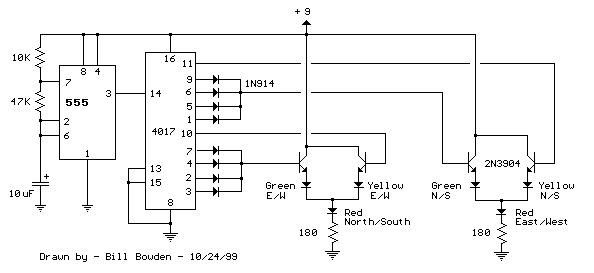
The LED traffic Light circuit controls 6 LEDs (red, yellow and green) for both north/south directions and east/west directions. The timing sequence is generated using a CMOS 4017 decade counter and a 555 timer. Counter outputs 1 through 4...
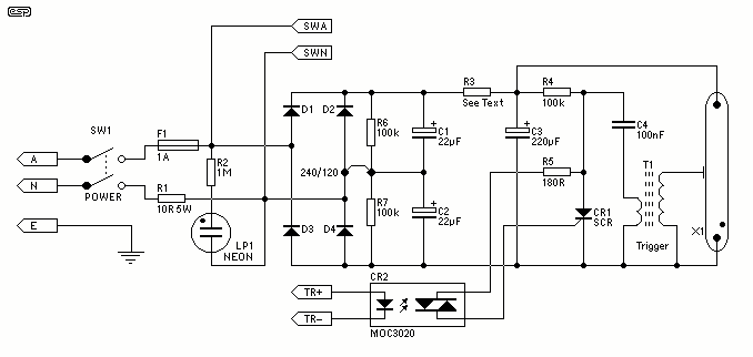
Since the circuit operates at greater than mains potential and is not isolated by a transformer, it is extremely dangerous. The DC operating potential is about 340V, and there is more than enough stored charge to kill you many...
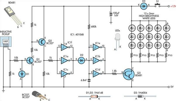
A useful timing strobe can be constructed using high-brightness LEDs and a few common components. Ignition pulses from the number 1 cylinder high-tension lead are used to trigger the circuit via a homemade inductive pickup. Transistors Q1 and Q2...
The design modifications were primarily selected to enhance the system's weight efficiency. The majority of weight reduction was achieved through the implementation of a single board design, transitioning to single battery operation, and directly mounting the battery onto the...
The circuit detects a ringing signal tone and provides both light and sound indicators. It is user-friendly and of good quality, and it does not require a power supply to operate, functioning solely to detect the ringing signal. The described...
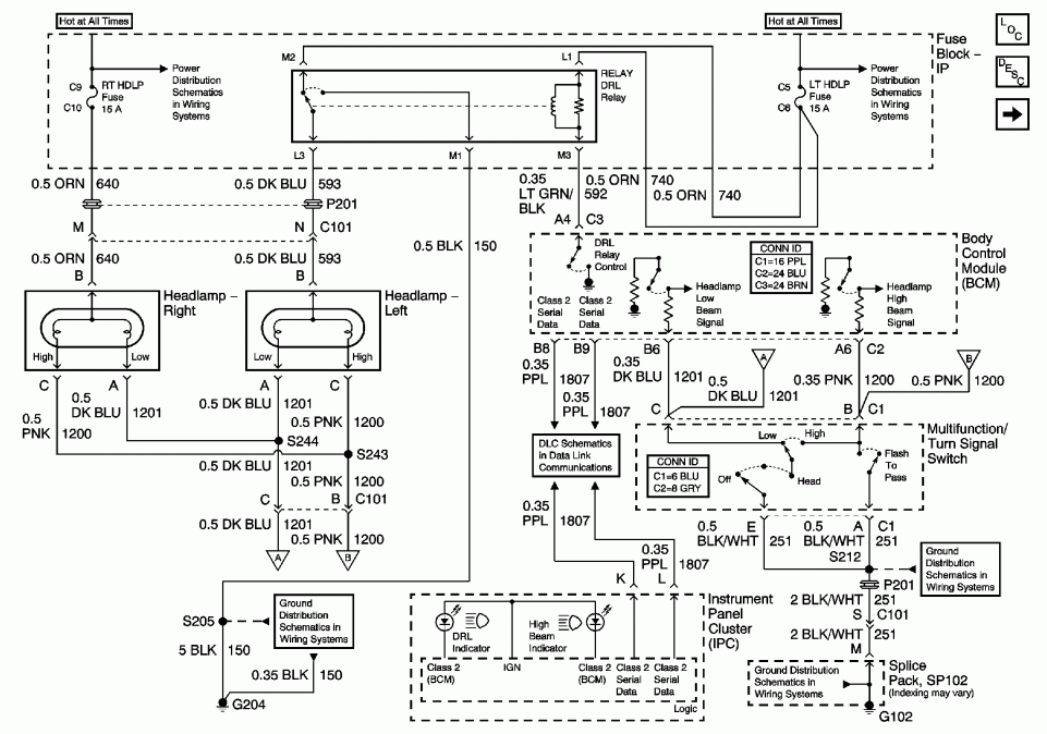
A 2001 Chevrolet Cavalier has experienced a failure in one of the low beam headlights. Despite replacing the bulb, the headlight remains non-functional. Additionally, when the vehicle is shifted into gear, the daytime running lights flash multiple times before...
Warning: include(partials/cookie-banner.php): Failed to open stream: Permission denied in /var/www/html/nextgr/view-circuit.php on line 713
Warning: include(): Failed opening 'partials/cookie-banner.php' for inclusion (include_path='.:/usr/share/php') in /var/www/html/nextgr/view-circuit.php on line 713