
Auto Microphone Muter

There is a burglar detection product that is a laminated plastic film affair with metal strips inside that normally don't touch each other, but anything over about 5 pounds of force causes them to touch. The strips are brought out to leads to sense the contact. These contact mats are normally placed under carpets in places that intruders are likely to step. The pressure sensitive mats are available in two foot by three foot sections for a reasonable price at most burglar alarm suppliers. (Ask to talk to the installation tech, not the sales person!)
You can't just use the mat contacts to open and close the mike lines directly because they would almost certainly cause unendurable hum, buzz and noise pickup. To avoid the noise, you need to use some switch element that is controlled by the mat contacts, but that does not couple the mat noise or clicks to the signal path. It turns out that there are lots of ways to do this, and I'll later describe several ways to do this.
The mechanical setup at the mike itself is as important as the electronics, because it HAS to work properly for the way you use the mike and the way it's set up and transported to and from gigs. The pressure switch mat should be placed on the floor where you'll stand, and a rubber or carpet mat over it to protect the pressure mat from hard edged shoes. There is a small box containing the electronics that is attached to the mike stand in some way. I used velcro strips attached to the box for this. The box needs connectors for the signal cable from the mike, the switched audio cable to the sound board or PA, and a connector for the pressure strip contacts. It's fully possible to build these connections into the mike stand base if you have your own, or to use an external box like I did. With its input low, the output of the 7->6 inverter drives the input of the 5->4 and 11->12 inverters high, so their outputs go low. The output of the 11->12 inverter pulls down on the cathode of the series H11F3's LED at pin 2. Pin 1 of this opto is tied to R3, which limits the current through it to about 16 ma. The LED causes the photoFET in the series H11F3 to conduct, so sound goes through to the PA connector.
Meanwhile, the output of the 5->4 inverter is also low, which causes the output of the 3->2 inverter to be high. This pulls the cathode of the shunt H11F3 module up to the supply voltage. Its anode is pulled up to the battery voltage by R2, and so no current flows, and its photoFET looks like an open circuit; no signal is shunted.
When the pressure mat is unloaded, its contact opens, and C1 charges through R1. When it reaches a bit above 1/2 of the battery voltage, the 7->6 inverter changes state, and all of the rest of the inverters also change state, driven by the 7->6 inverter output. The 11->12 inverter output is high, so the series H11F3 opto goes to the "off" state, letting no signal through to the PA connector. The 3->2 inverter output is low, turning on the LED in the shunt H11F3 and causing its photoFET to go to a low resistance, effectively shorting the PA connector and preventing noise and hum from getting on to the cable. Note that the ground symbol does NOT connect to the signal ground. In fact, nothing about the Mike Muter except the photoFets connect to the signal or signal ground at all. This keeps all the problems with noise at bay.
If you're the kind of guitarist that likes to jump around, you might like the mike not to cut off while you're in the air. If so, you can use a big capacitor and resistor for R1 and C1. If you make the time constant about 2 seconds, you'll get about 1 second of "mike on" after you step off the mat. The turn-on when you step back onto the pressure mat should be almost instant.
So what are the circuit values? R1 and C1 are chosen for the turn-off delay. If you use a ceramic 1uF capacitor for C1, you can get about a 1/2 second delay from a 510K resistor, about one full second from a 1M. The current limiting resistors are chosen for the battery voltage you use. Good choices are four AA cells, giving 6V and long life, or 9V for compatibility with other pedal batteries. The forward voltage of the LED's in the H11Fx series is typically 1.1V, so for a 6V battery, a 270 ohm resistor gives about 16 ma of LED current. If you choose a 9V battery, a 470 ohm resistor will give about the same LED current. Clearly, there are a thousand ways to do this. You could even do it the Brute Force way, and just put a stomp switch into a box on the floor to punch the mike on and off as you tapdance away and toward the mike stand. However, you have to think about doing things like that, and unless you're a lot more chilled out and together on stage than I am, you'll forget at some crucial moment. The advantage of the smart Mike Muter is that it's automatic. You only have to get yourself to and from the microphone, it takes care of the rest.
The described microphone muting circuit utilizes a pressure-sensitive mat to detect when a performer steps on or off it, effectively controlling the microphone's audio signal path based on the presence of the user. The core of the circuit employs a series of inverters and opto-isolators (H11F3) to manage the switching of the audio signal. When the performer steps on the mat, the circuit allows the microphone's signal to pass through to the PA system. Conversely, when the performer steps away, the circuit mutes the microphone to prevent unwanted noise from being amplified.
The circuit's design features a combination of resistors and capacitors to create a time delay for the microphone muting function, allowing for a brief period during which the microphone remains active after the performer steps off the mat. This is particularly beneficial for performers who tend to move around during performances. The choice of component values is critical; for instance, using a 1uF capacitor with a 1M resistor yields an approximate one-second delay before muting the microphone.
The mechanical implementation involves careful placement of the pressure mat beneath the performer's feet, protected by a secondary mat to ensure durability. The electronic components are housed in a compact enclosure attached to the microphone stand, ensuring ease of access and setup. The system is designed to minimize noise and interference, with careful consideration given to grounding and signal pathways to maintain audio integrity.
This innovative approach to microphone control enhances the performance experience by allowing musicians to focus on their art without the distraction of manual microphone management. The automatic nature of this system provides a seamless transition between singing and instrumental performances, making it a valuable addition to any performing setup.If you've crossed the line and play guitar or bass and also sing in a band, you're almost certain to have run into the situation that you step away from the mike to do a solo (or one of those neato, expressive dance steps, or a facial impression of the pain you're pouring out to make these dulcet tones...), and had the mike pick up some unfortunate noise to funnel into the PA. You may even have fumbled for the mike mute switch as you stepped away and back to it, but that's almost terminally clumsy, as you have your hands full of your instrument.
Wouldn't it be nice if the microphone was only "listening" when you stepped up to it? Muting a microphone is simple. Knowing when is hard. The real trick is having the microphone be smart enough to figure out that you want to sing now. When my amp-tech friend first asked me to figure out a way to mute a mike when the singer stepped away, I went on these little flights of fancy with infrared motion detectors, ultrasonic range finders and other even less practical stuff, but what finally came out was a cross pollenization idea. Most singer/guitarists stand up to sing (except for you intimate acoustic types!) and that means they touch the floor.
The home burglar alarm industry has come up with a simple and durable way to detect people standing on a floor. There is a burglar detection product that is a laminated plastic film affair with metal strips inside that normally don't touch each other, but anything over about 5 pounds of force causes them to touch.
The strips are brought out to leads to sense the contact. These contact mats are normally placed under carpets in places that intruders are likely to step. The pressure sensitive mats are available in two foot by three foot sections for a reasonable price at most burglar alarm suppliers. (Ask to talk to the installation tech, not the sales person!) You can't just use the mat contacts to open and close the mike lines directly because they would almost certainly cause unendurable hum, buzz and noise pickup.
To avoid the noise, you need to use some switch element that is controlled by the mat contacts, but that does not couple the mat noise or clicks to the signal path. It turns out that there are lots of ways to do this, and I'll later describe several ways to do this.
The mechanical setup at the mike itself is as important as the electronics, because it HAS to work properly for the way you use the mike and the way it's set up and transported to and from gigs. The pressure switch mat should be placed on the floor where you'll stand, and a rubber or carpet mat over it to protect the pressure mat from hard edged shoes.
There is a small box containing the electronics that is attached to the mike stand in some way. I used velcro strips attached to the box for this. The box needs connectors for the signal cable from the mike, the switched audio cable to the sound board or PA, and a connector for the pressure strip contacts. It's fully possible to build these connections into the mike stand base if you have your own, or to use an external box like I did.
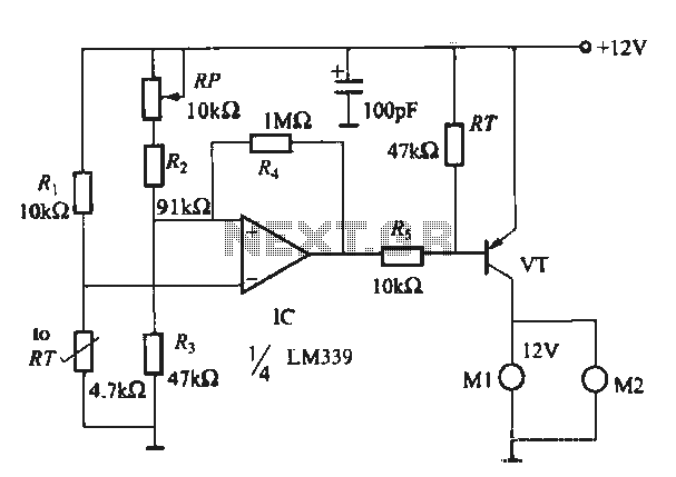
With its input low, the output of the 7->6 inverter drives the input of the 5->4 and 11->12 inverters high, so their outputs go low. The output of the 11->12 inverter pulls down on the cathode of the series H11F3's LED at pin 2. Pin 1 of this opto is tied to R3, which limits the current through it to about 16 ma. The LED causes the photoFET in the series H11F3 to conduct, so sound goes through to the PA connector.
Meanwhile, the output of the 5->4 inverter is also low, which causes the output of the 3->2 inverter to be high. This pulls the cathode of the shunt H11F3 module up to the supply voltage. Its anode is pulled up to the battery voltage by R2, and so no current flows, and its photoFET looks like an open circuit; no signal is shunted.
When the pressure mat is unloaded, its contact opens, and C1 charges through R1. When it reaches a bit above 1/2 of the battery voltage, the 7->6 inverter changes state, and all of the rest of the inverters also change state, driven by the 7->6 inverter output. The 11->12 inverter output is high, so the series H11F3 opto goes to the "off" state, letting no signal through to the PA connector.
The 3->2 inverter output is low, turning on the LED in the shunt H11F3 and causing its photoFET to go to a low resistance, effectively shorting the PA connector and preventing noise and hum from getting on to the cable. Note that the ground symbol does NOT connect to the signal ground. In fact, nothing about the Mike Muter except the photoFets connect to the signal or signal ground at all.
This keeps all the problems with noise at bay. If you're the kind of guitarist that likes to jump around, you might like the mike not to cut off while you're in the air. If so, you can use a big capacitor and resistor for R1 and C1. If you make the time constant about 2 seconds, you'll get about 1 second of "mike on" after you step off the mat.
The turn-on when you step back onto the pressure mat should be almost instant. So what are the circuit values? R1 and C1 are chosen for the turn-off delay. If you use a ceramic 1uF capacitor for C1, you can get about a 1/2 second delay from a 510K resistor, about one full second from a 1M. The current limiting resistors are chosen for the battery voltage you use. Good choices are four AA cells, giving 6V and long life, or 9V for compatibility with other pedal batteries.
The forward voltage of the LED's in the H11Fx series is typically 1.1V, so for a 6V battery, a 270 ohm resistor gives about 16 ma of LED current. If you choose a 9V battery, a 470 ohm resistor will give about the same LED current. Clearly, there are a thousand ways to do this. You could even do it the Brute Force way, and just put a stomp switch into a box on the floor to punch the mike on and off as you tapdance away and toward the mike stand.
However, you have to think about doing things like that, and unless you're a lot more chilled out and together on stage than I am, you'll forget at some crucial moment. The advantage of the smart Mike Muter is that it's automatic. You only have to get yourself to and from the microphone, it takes care of the rest. 🔗 External reference
Related Circuits
An easy automatic battery charging circuit is presented, which can automatically power off when the battery is fully charged. This design prevents overcharging. The automatic battery charging circuit operates by utilizing a voltage sensing mechanism to monitor the battery's charge...
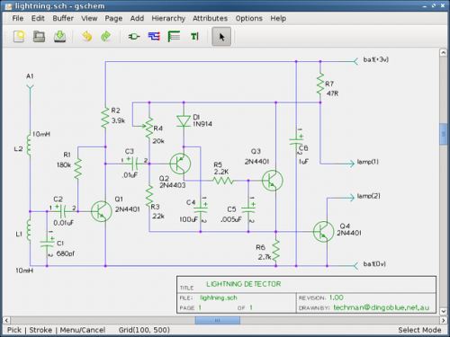
Are you looking for a free schematic and PCB design tool? The gEDA project has produced and continues to work on a complete GPL licensed suite and toolkit for electronic design. The gEDA project offers a comprehensive suite of tools...
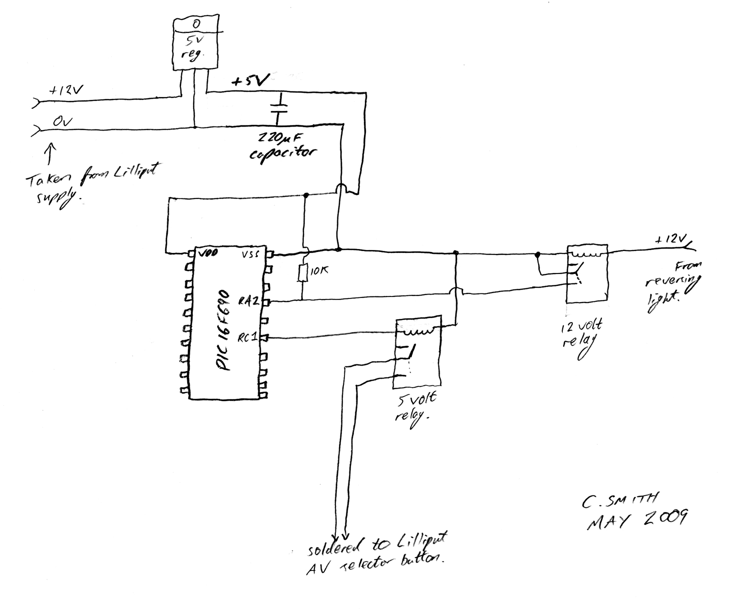
There have been numerous discussions regarding the Lilliput's inability to automatically switch, despite the presence of this feature in the secret menu. The Lilliput display is a versatile device often used in various applications, including professional video production and...
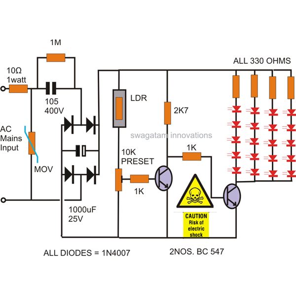
The power supply utilized in this circuit is of the capacitive type, eliminating the need for a transformer and allowing for a compact design that can be easily installed in small spaces. The circuit employs LEDs instead of traditional...
When running large-scale software or games, a computer's internal temperature can increase significantly, especially during hot summer months. Although the machine is equipped with a CPU and graphics card fan, poor hot air circulation prevents immediate removal of heat...
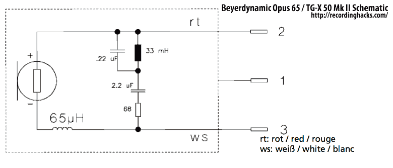
The Mk II was a second-generation version of the TG X 50. Both were dynamic microphones intended for bass instruments and kick drums. The primary difference between the two versions was the introduction of a passive EQ filter in...