
simple led automatic daynight lamp
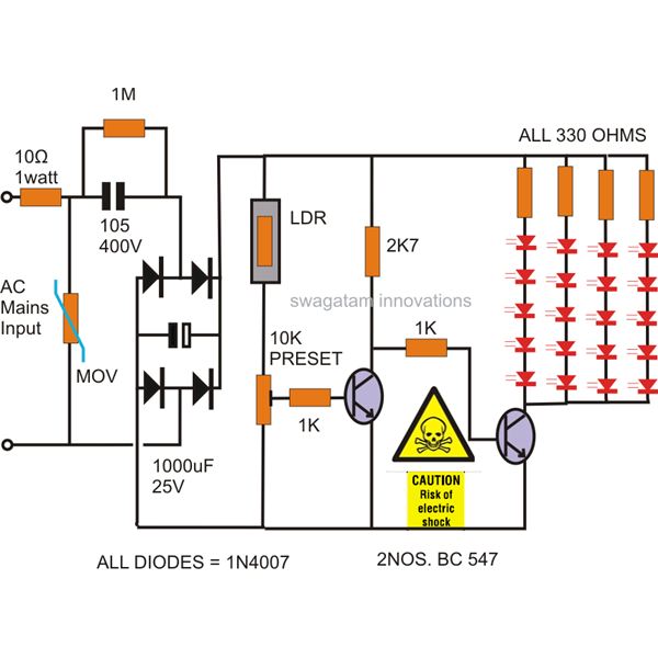
The circuit design features a capacitive power supply that operates without a transformer, making it suitable for compact installations in various environments. The use of LEDs significantly enhances energy efficiency compared to traditional lighting solutions, with the option to use white LEDs for improved illumination effectiveness. The inclusion of a 10-ohm resistor serves a critical role in managing voltage transients; this resistor limits the inrush current, thereby safeguarding sensitive components downstream from potential overvoltage conditions.
The MOV acts as a protective element, functioning to absorb voltage spikes and divert excess energy to ground, thus preventing damage to the circuit during transient events. This combination of the 10-ohm resistor and the MOV ensures robust protection against electrical surges, contributing to the longevity and reliability of the device.
The operational mechanism of the circuit hinges on the light-dependent resistor (LDR), which adjusts its resistance based on ambient light levels. When light intensity decreases, the resistance of the LDR diminishes, leading to an increase in voltage across the variable resistor connected to the comparator transistor. Once this voltage reaches a critical saturation point, the transistor activates, allowing current to flow and turning on the LED. This automatic switching mechanism provides convenience and energy savings, as the lamp only operates when needed, responding dynamically to changes in environmental lighting conditions.
Overall, this circuit exemplifies an efficient, compact design that leverages modern components to achieve effective automatic lighting control.The power supply used here is a capacitive type, thus no transformer is incorporated making the circuit very compact and fixable in any small corner of the particular premise. The use of LEDs in place of a filament bulb makes the application very powereconomicand efficient. The proposed LED automatic day night lamp switch circuit diagram shows red LED being used, however white LEDs would suit the application better, as that would help illuminate the area better than the red LEDs. The 10 Ohms resistor helps to cancel out the initial surge or the voltage rush that might otherwise be potentially harmful to the further stages of the circuit.
The MOV or the varistor placed after the 10 Ohm resistor emhances the protection feature of the unit and grounds all surges that might sneak in after the 10 Ohm resistor. The first transistor is wired up as a comparator, which compares the potential difference across the variable resistor andconductswhen the voltage across it rises to saturation levels.
Theabove rise in the voltage level takes place when the relevant magnitude of light falls on the LDRsurface. Once the resistance of the LDR falls below the set threshold due to higher ambient light, the transistor conducts.
🔗 External reference
Related Circuits
In conventional white LED design, the Max1916 low-dropout bias supply for white LEDs serves as a high-performance alternative to simple ballast resistors. The Max1916 is an integrated circuit designed to provide a stable and efficient bias supply for white LEDs....
An LED is usually a series resistor needed to ensure that the LED does not get too much power. The disadvantage of such resistance is that the current through the LED and thus the brightness changes as the voltage...
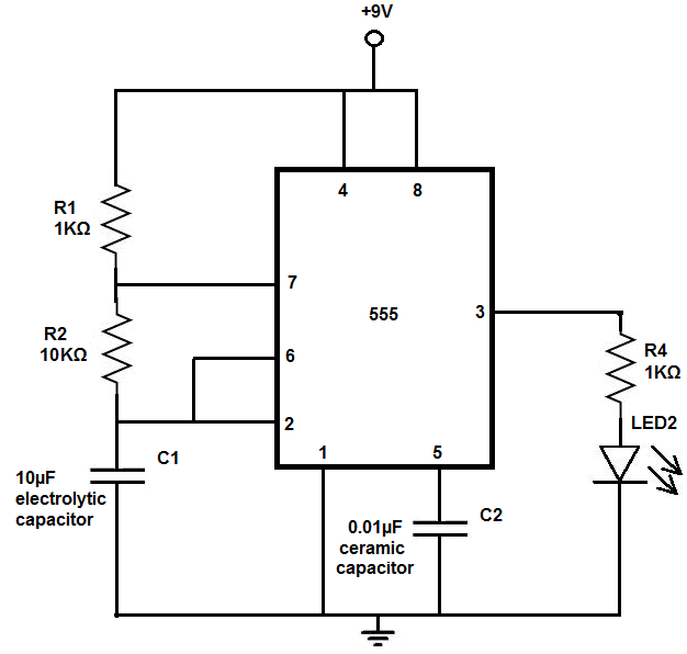
The 555 timer chip is a versatile integrated circuit (IC) that, when connected correctly, can generate pulses of current at specific intervals determined by a resistor-capacitor (RC) network. In this mode, the LED does not remain constantly lit; it...

The voltage to be measured is digitized in an analog-to-digital (A/D) converter and then displayed in three decimal digits. The display consists of three groups of 10 LEDs. The meter can only be used for measuring direct voltages. The...

This circuit is designed for operation in the 80m band. It utilizes a 365-pF variable capacitor, specifically intended for the broadcast band, which should be equipped with a vernier drive featuring a six-to-one tuning ratio. This configuration enhances the...

This document presents a circuit diagram for a simple and easy-to-construct battery level indicator. Typically, in mobile phones, battery levels are shown in either dot or bar format, allowing users to easily recognize the battery status. The battery level indicator...