
Easy Auto power battery charging circuit
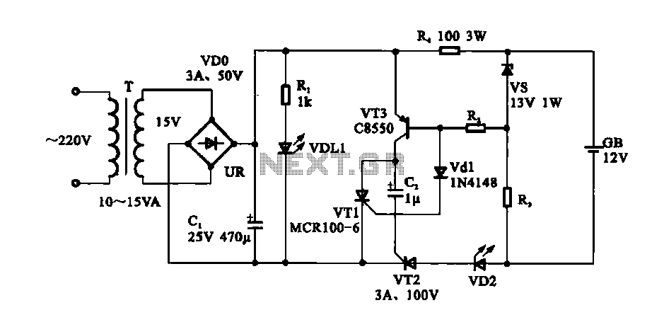
The automatic battery charging circuit operates by utilizing a voltage sensing mechanism to monitor the battery's charge level. The primary components typically include a transformer, rectifier, voltage regulator, and a microcontroller or comparator for sensing the battery voltage.
The transformer steps down the AC voltage from the mains supply to a lower AC voltage suitable for charging the battery. The rectifier, usually a bridge rectifier configuration, converts the AC voltage to DC voltage, which is necessary for charging the battery. The output of the rectifier is then filtered using capacitors to smooth out the ripples, providing a stable DC voltage.
A voltage regulator may be employed to ensure that the voltage supplied to the battery does not exceed its rated charging voltage. This is crucial for preventing damage to the battery and ensuring a safe charging process.
The microcontroller or comparator continuously monitors the battery voltage. When the battery reaches its full charge voltage, the circuit automatically disconnects the charging current, effectively shutting off the power to the charger. This feature is essential in preventing overcharging, which can lead to battery overheating, reduced lifespan, or potential hazards.
Additional features may include LED indicators to show the charging status and a fuse for overcurrent protection. The design can be tailored to accommodate various battery types, such as lead-acid, lithium-ion, or nickel-cadmium, by adjusting the charging parameters accordingly.
Overall, this automatic battery charging circuit provides a reliable and efficient solution for maintaining battery health and performance while ensuring user safety.Easy Auto power battery charging circuit Is shown as a simple automatic power battery charging circuit, the circuit can automatically power off when the battery is fully charge d, it will not overcharge phenomenon.
Related Circuits
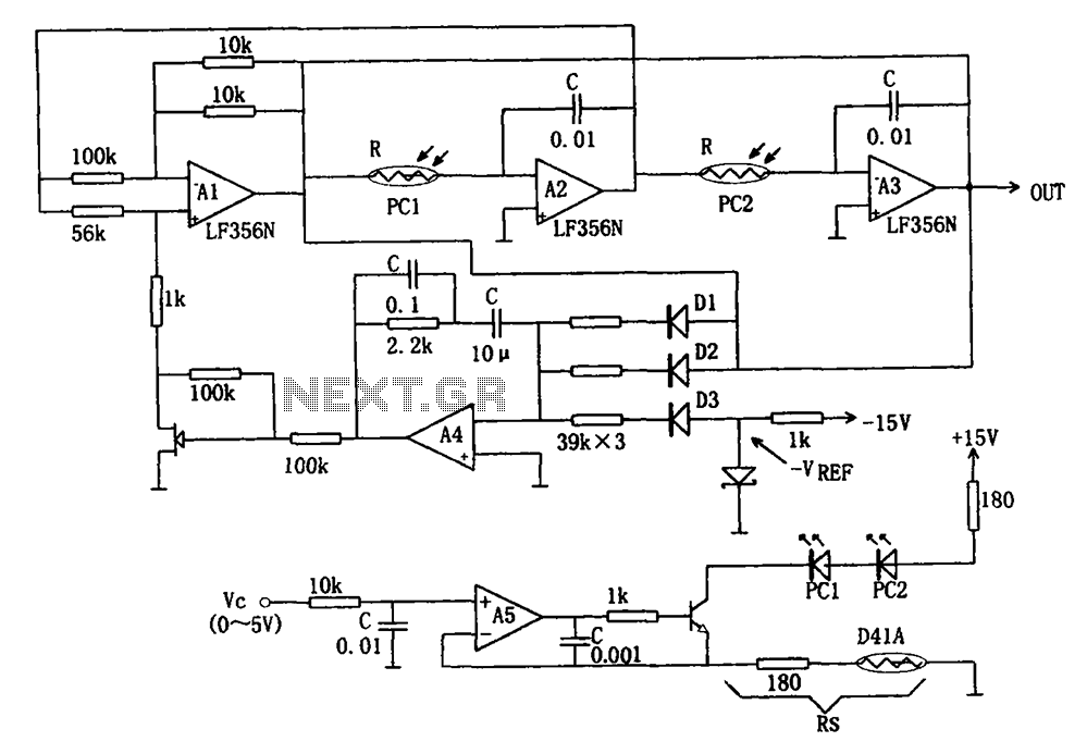
The wideband sinusoidal voltage-controlled oscillator circuit is designed such that the oscillation frequency is determined by an integrating resistor R and a capacitor C. The voltage-controlled oscillator is constituted by the applied control voltage Vc and a control resistor...

This circuit is designed for tone control utilizing a three-band equalizer. It is based on the LF351 single-chip operational amplifiers. The circuit features three adjustable ranges: bass, mid, and treble controls. The equalizer allows for approximately +/-20 dB of...
Automatic gain control. A control circuit that automatically changes the gain (amplification) of a receiver. Automatic Gain Control (AGC) is a crucial circuit used in various electronic devices to maintain a consistent output level despite variations in input signal strength....
The Motorola company's MC14440 CMOS integrated circuit is designed for timing and displaying calendar functions. It utilizes a 32.768 kHz NT cutting type quartz crystal along with fine-tune capacitance to generate time-based signals. The display circuit operates on a...
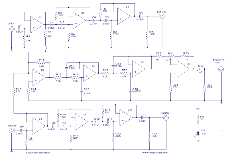
This is the schematic diagram of an operational amplifier (op-amp) based subwoofer filter. Audio frequencies below 200 Hz are typically categorized within the subwoofer range, indicating that a subwoofer filter should have a cutoff frequency around 200 Hz. The...

This circuit exhibits an exceptionally fast high-frequency response, as demonstrated by applying a 100 kHz square wave to the input. All graphs were produced using Tina Pro. The circuit's design is optimized for high-frequency applications, showcasing rapid response times that...
Warning: include(partials/cookie-banner.php): Failed to open stream: Permission denied in /var/www/html/nextgr/view-circuit.php on line 713
Warning: include(): Failed opening 'partials/cookie-banner.php' for inclusion (include_path='.:/usr/share/php') in /var/www/html/nextgr/view-circuit.php on line 713