
Auto OFF Light
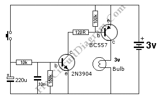
The Auto OFF Light circuit is designed to provide a temporary illumination of a bulb after a switch is activated. The operation of the circuit relies on a timing mechanism that allows the bulb to remain lit for a predetermined duration, enhancing user convenience in various applications, such as in hallways or bathrooms.
The core components of this circuit typically include a switch, a resistor (10kΩ), a capacitor, and a light bulb. When the switch is pressed, it initiates the charging of the capacitor through the resistor. The time the bulb stays lit is primarily determined by the RC time constant, which is a product of the resistance (R) and capacitance (C) in the circuit.
To increase the ON time, the value of the resistor can be adjusted. A higher resistance, such as 10kΩ, will result in a longer charging time for the capacitor, thus extending the duration the bulb remains illuminated. The formula for the time constant (τ) is given by τ = R × C, where τ is the time in seconds, R is the resistance in ohms, and C is the capacitance in farads.
The circuit may also include a diode to prevent back EMF from damaging components when the bulb is turned off. The light bulb can be of various types, including incandescent or LED, depending on the desired brightness and energy efficiency.
In summary, the Auto OFF Light circuit is a practical design that provides temporary lighting, with the ability to adjust the duration of illumination through component selection, making it suitable for a variety of lighting applications.This is Auto OFF Light circuit. After the switch is pressed, the bulb is kept illuminated for a few seconds. To increase the ON time, The 10k should be. 🔗 External reference
Related Circuits
A low-pass filter is a stable state-space system that has an input and produces an output. If the input is a quasi-periodic signal, the output will be the same quasi-periodic signal with a phase shift. The key difference is...
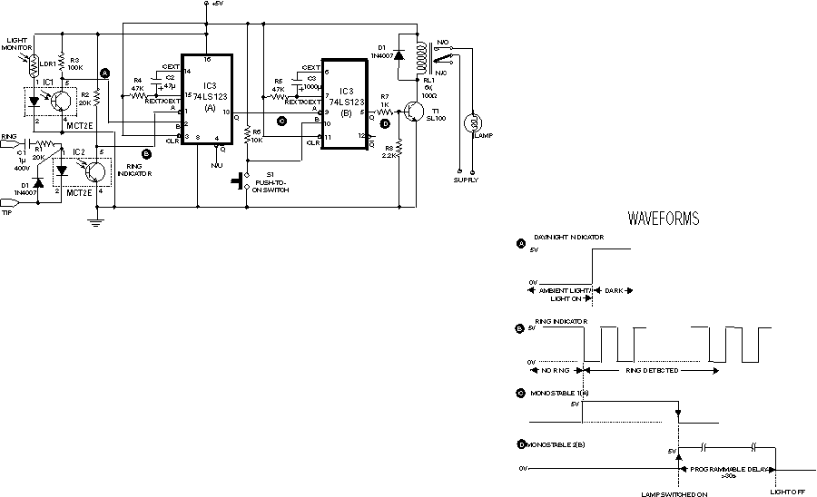
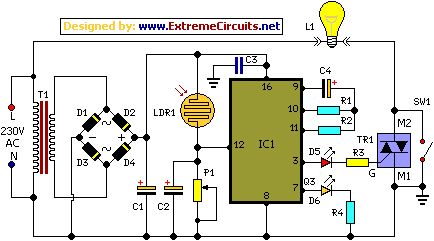
The circuit shown here is used to switch on a lamp when the telephone rings, if the ambient light is insufficient. The circuit uses only two ICs and it can be implemented very easily. A light dependent resistance (LDR),...
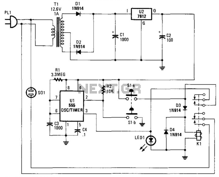
Suitable for cutting off an appliance or other AC load, this timer will cut the AC power after a period determined by R1/C3, as shown, for about 40 minutes. K1 is a relay that should handle about 10 A....
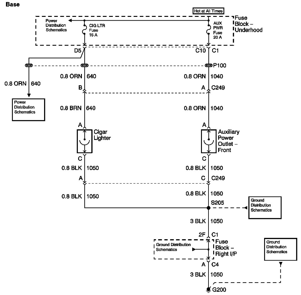
The provided information includes a fuse block diagram with the Auxiliary Power (Aux Pwr) fuse highlighted. It is advisable to check both sides of the fuse using a test light or multimeter to ensure functionality. It is assumed that...
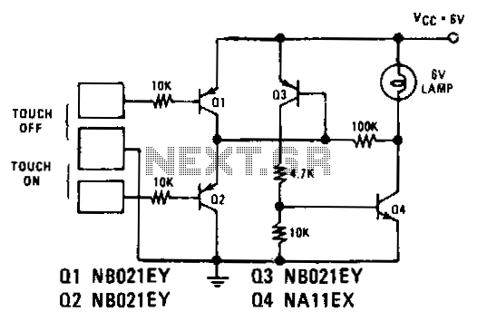
Transistors Q1 and Q2 control latches Q3 and Q4 to switch on the lamp. A high resistance from touching the electrode biases Q1 or Q2 on, setting or resetting the latch. In this circuit, transistors Q1 and Q2 function as...
Most thefts occur after midnight when individuals enter the second phase of sleep known as paradoxical sleep. An energy-saving circuit has been designed to deter theft attempts by illuminating potential entry points, such as the kitchen or backyard, around...