
Appliance Cutoff Timer
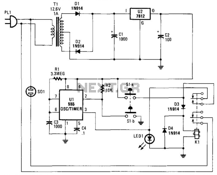
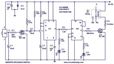
The described circuit utilizes a timer mechanism to control the power supply to an AC load, effectively enabling or disabling the load after a predetermined duration. The timer is configured using a resistor (R1) and a capacitor (C3), which together set the timing interval to approximately 40 minutes. This timing function is critical for applications where automatic shut-off is required to prevent overheating, energy wastage, or safety hazards.
The relay (K1) serves as the switching device, capable of handling a load current of up to 10 A, making it suitable for a variety of household appliances. The relay is activated by the timer circuit, which closes the relay contacts to allow current flow to the load when the timer initiates the cycle. When the timing period expires, the relay is deactivated, cutting off the AC power supply to the load.
Activation of the timer is achieved through the use of momentary switches (S1A and S1B). These switches are designed to be pressed briefly to start the timing cycle, providing user control over when the timer begins its countdown. The momentary nature of these switches ensures that the timer starts only when intended, preventing accidental activation.
Overall, this circuit design is efficient and practical for applications requiring timed control of AC loads, ensuring that devices can operate for a set duration before being automatically turned off. The combination of resistive and capacitive components in the timing circuit allows for precise control over the timing interval, while the relay and momentary switches provide robust operational capabilities. Suitable for cutting off an appliance or other ac load, this timer will cut the ac power after a period determined b y R1/C3, as shown, for about 40 minutes. Kl is a relay that should handle about 10 A. SlA and SIB is a momentary switch that starts the timer cycle. 🔗 External reference
Related Circuits
The 555 timer is a versatile component that can be utilized as a timer and configured to produce a specific frequency. In Part II of Electronic Project I, a circuit was created to make an LED flash. This time,...
This is a lamp timer capable of operating two separate relay switches. Outputs can be in three (or restricted to two) states: OFF, delayed ON and constant ON. Delayed ON mode is indicated by the LEDs. The source code...
The following circuit illustrates a Cat and Dog Repellent Timer Circuit Diagram. Features include the capability to maintain a deep cycle battery charged by a solar panel. The Cat and Dog Repellent Timer Circuit is designed to provide a humane...
555 Timer TV Remote Controlled Home Appliance Circuit Diagram. Features: 555 timer IC to avoid fast switching. You can only switch the circuit. The 555 timer integrated circuit (IC) is a versatile component widely used in various electronic applications, including...
This door open alarm electronic project is designed using a linear hall effect device and a 555 timer circuit. The project utilizes the TL3103 linear hall effect device for detecting the angle of rotation. The TL3103 is positioned within...
This easy electronic buzzer circuit is built based on a timer that operates to generate frequency. The IC timer NE555 is used as an astable multivibrator operating at approximately 1 kHz, producing a sound when powered on. The sound...