
Auto Shut Off Tone Generator
The auto shut-off tone generator circuit is a practical application of timer ICs, providing an effective means of sound generation for security purposes. The dual configuration of the 555 timers allows for both frequency modulation and timing control, enhancing the functionality of the device. The astable timer (U2) operates continuously, generating a square wave output that is transformed into an audible signal through the loudspeaker. The frequency of the sound can be fine-tuned by adjusting the resistors and capacitor associated with U2, allowing for customization based on specific requirements.
The monostable timer (U1) serves a critical role in ensuring that the alarm is only active for a predetermined duration. Upon activation, U1 generates a pulse that temporarily disables U2, maintaining the alarm's operational integrity. The timing components associated with U1 are selected to achieve a precise delay, ensuring that the system adheres to the desired operational parameters.
Overall, this tone generator project exemplifies the versatility of 555 timer ICs in electronic design, showcasing their ability to perform multiple functions within a single circuit. The simplicity of the components used, combined with the effectiveness of the design, makes this project an excellent choice for those seeking to implement a portable alarm system.In this auto shut off tone generator project, once the switch to the 9V power supply is connected, the alarm will trigger at a frequency of approximately 1.27 kHz. It will remain ON for a duration of approximately 170 seconds or 2.8 minutes before it stopped. This is a typical home burglar alarm system of which once the alarm is triggered ON, it will not be shut OFF until the duration of time set has elapsed.
This project is useful when built as one can carry it along wherever one goes or placed it in a vehicle. In times of emergency, one can easily switched ON the switch and the loud speaker will emit a loud sound that will frighten the uninvited guest.
It is based on two 555 timer ICs or one single 556 timer IC(which contains two 555 timers). In this schematic, two 555 timers are used. U2 is configured as a timer in astable mode. Once triggered, it will emit a frequency from its output at pin 3 that will drive a Q1 transistor. Q1 transistor will turn ON and OFF according to the frequency of the circuit. It will in turn used to drive a 8 ohm loud speaker to emit a loud audible sound. The astable frequency of circuit U2 is given by the formula of 555 timer as shown below. f = 1.44/[47K + 2(33K)][10nF] = 1.27 kHz The frequency of the sound can be adjusted by changing the values of R3= 47K, R4= 33K and capacitor C1=10nF. Change the values of these components and by using the formula for astable mode, the frequency of the sound can be obtained.
U1 circuit is used as a delay circuit which is configured as a monostable mode. It is a one shot multivibrator that will generate a pulse at its output at pin 3 which will disable the astable circuit U1. In this circuit, pin 2 of U1 will go to logic 0 when the power supply is connected via the capacitor E1 and hence circuit U2 is immediately triggered.
The pulse duration of the monostable circuit is given by the formula: T = 1.1(330K)(470uF) = 170 seconds Once this timing is up, it the pulse output will disable the astable circuit of U2.
Related Circuits
T1 and T2 in the circuit form the inherent oscillator, while T3 serves as the output stage. The network consists of a high-pass filter (C3, C4, R6, and R7) and a low-pass filter. The output from this network is...
This circuit is a melody generator circuit diagram controlled by the UM66 IC. The UM66 is a CMOS IC designed for applications such as call bells, telephones, and toys. It features a built-in ROM programmed to play music and...
In certain locations near the reservoir or well, when the water level is constrained by the water towers, there is a need for simultaneous monitoring of the water towers and reservoirs as part of an automatic water control system....
The two optical sensors will provide a count of individuals to the microcontroller, which will relay this value to MCU-II. The microcontroller will detect the entrance of any person through high-to-low pulse transitions on input pins A3 and A4. The...
A high-quality tone burst generator can be constructed using a 556 Dual Timer. The first half of the timer can be configured as a one-shot, while the second half can function as an oscillator. The 556 Dual Timer is an...
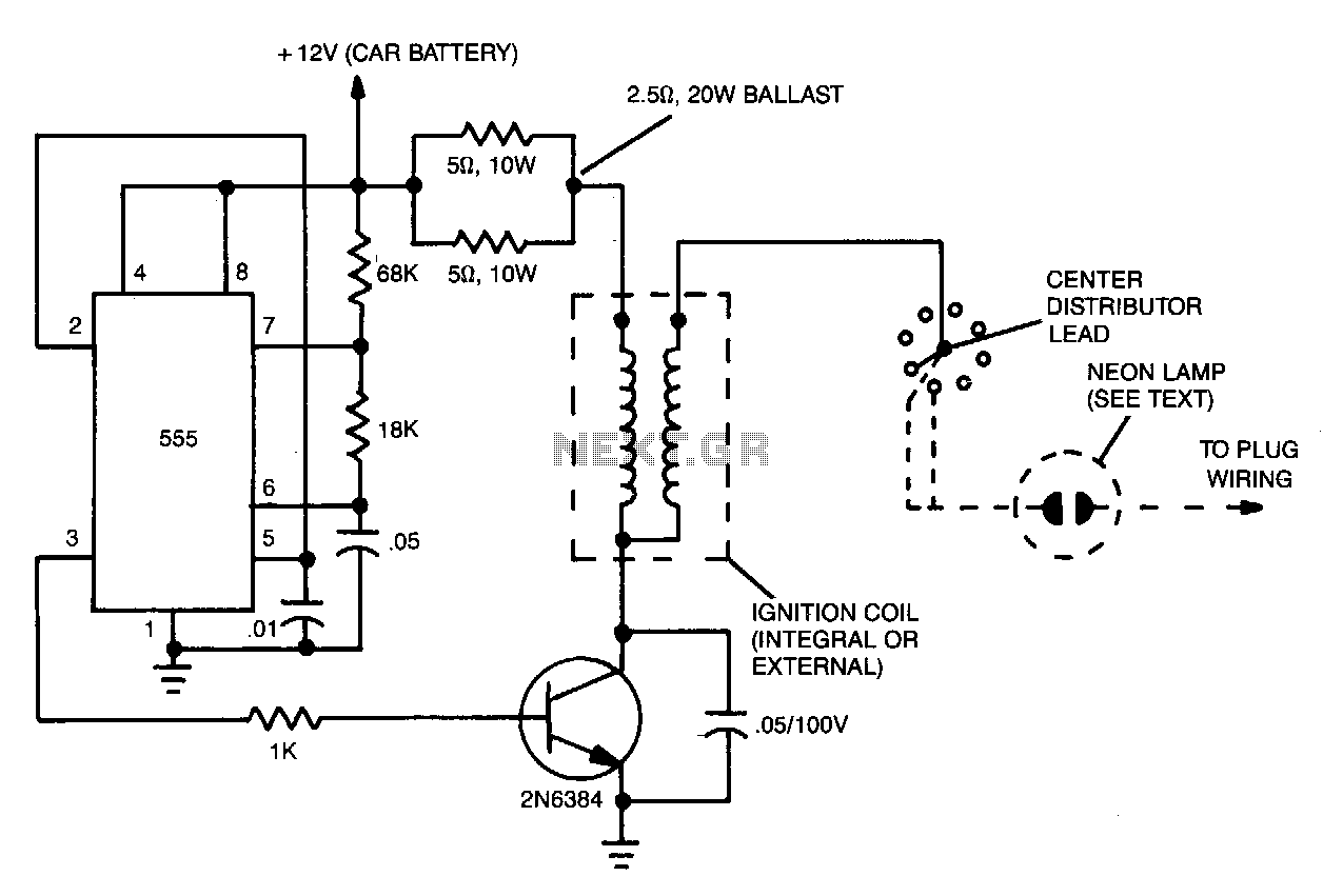
The ignition substitute provides a constant power source for the ignition coil. Its frequency, 0.5-1.0 kHz, is that used by an 8-cylinder engine with an idling speed of 650 RPM, and the unit provides a rapid spark at a...