
autodetects baud rate circuit MAX202 and PIC16C54
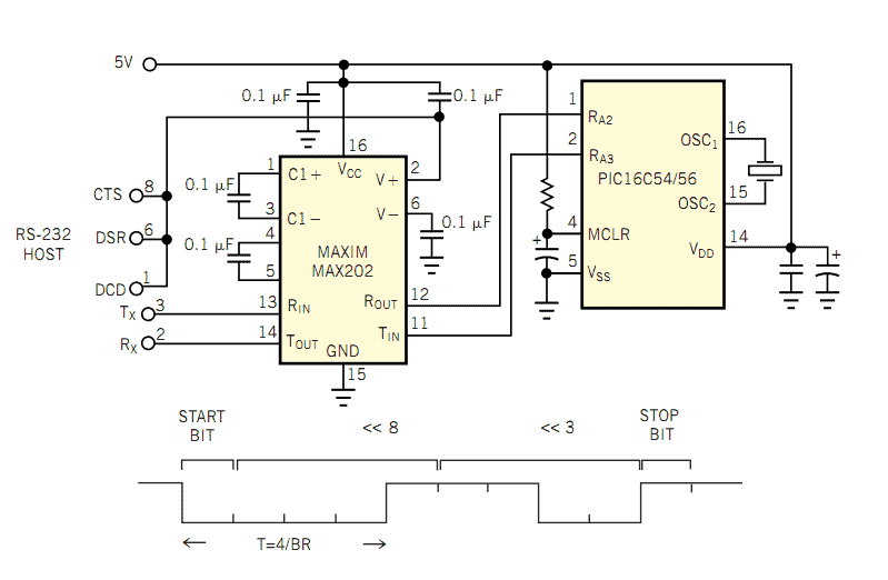
The RS-232 communication protocol is widely utilized for establishing serial communication between devices. The described circuit involves a microcontroller (mC) that is configured to adapt its serial port bit rate to match that of a host computer. The initial step in this process involves the host sending a known ASCII character to the microcontroller, which serves as a reference for determining the transmission bit rate.
Upon receiving the start bit, indicated by a transition from high to low voltage on the transmission line, the microcontroller initiates a timer. This timer measures the duration until the line transitions back to high, thereby allowing the microcontroller to calculate the bit rate based on the timing of the start and stop bits.
The microcontroller's timing mechanism is crucial for ensuring accurate data transfer. The timer is designed to increment its count every 4P/FOSC seconds, where P represents the prescaler value and FOSC denotes the clock frequency of the microcontroller. The formula T54/BR = N5FOSC/(BR3P) provides a means to derive the timer's value based on the bit rate (BR) and the clock frequency.
The application employs an 8-bit RISC microprocessor, and the ASCII code used for communication is 8 (38 hexadecimal). The choice of symbols for transmission is significant; using symbols with trailing zeros enhances the reliability of the communication by providing clear start and stop indicators.
Overall, this design exemplifies a robust method for synchronizing communication between a microcontroller and a host computer, ensuring that data is transmitted and received accurately based on dynamically calculated timing parameters.The popularity and easy access of RS-232 ports lend them to many communication projects. You can use a port as is” or as a tiny parallel port when the exchange uses only control lines. Before the asynchronous serial-data transfer between two devices can take place, you must ensure that both devices are configured to the same data format and transmission rate. Usually, the OS utility or application program on the host computer performs this task, which the OS or a combination of switches selects in the peripheral.
The design in Figure 1 and the accompanying software realize the requirement of automatically equalizing the speed of the parties by adapting the bit rate of a mC’s serial port to that of a host computer. The host sends a known ASCII code to a mC that estimates the bit rate of the transmission. The mC samples the receiving end of a transmission line. As soon as the line goes low, indicating a start bit, the mC clears the timer. After the line again goes high, the mC reads the timer’s value and uses this value to calculate the bit rate of a transmission.
The mC uses the calculated bit rate in a timing-delay loop for clocking out the data from the mC to the host computer during transmission and for sampling the incoming data during receiving mode. The time between those falling and rising edges on a transmission line depends, of course, on the transmitted ASCII symbol.
Its good practice to use a symbol with 2 k 21 zeros on the low side. Then, when you include the start bit, there are 2 k trailing zeroes. One timing unit is easier to derive by substituting a division with k right shifts. The application in Figure 1 uses an 8- bit RISC mP and an ASCII code of 8 (38 hex) to establish a serial communication. Any symbol that ends with 8H also works. The timer increments its value every 4P/FOSC seconds, where P is a prescaler factor and FOSC is the mP’s clock frequency.
Thus, the timer’s value after 4 bits have transmitted during the time between the falling and rising edge, is T54/BR, is N5FOSC /(BR3P), where BR is the bit rate. Now you can derive the 1-bit transmission time, which is a reciprocal of a t 🔗 External reference
Related Circuits
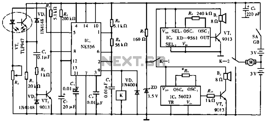
The circuit operates with VT1, which is an integrated infrared receiver, utilizing a red-emitting diode for perimeter triode reception. IC1 (NE556) functions as a dual timer, with R5, R6, and C5 forming an oscillation circuit that generates a frequency...
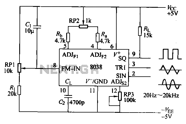
The ICL8038 function generator is an audio composition device that utilizes the ICL8038 integrated circuit. The resistance Ri potentiometer RP1 is used to determine the flow potential. Typically, the output is set to approximately 2Vcc / 3. Lowering the...
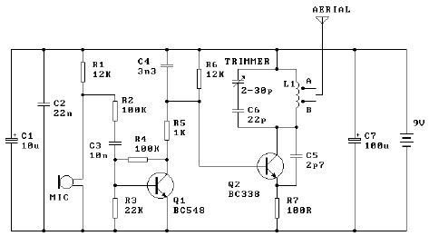
The tuned coil L1 has two output tap points for the antenna connection, labeled "A" and "B." Both outputs are low-level, allowing the user to select between a stable low range or a more unstable but higher range. Tap...
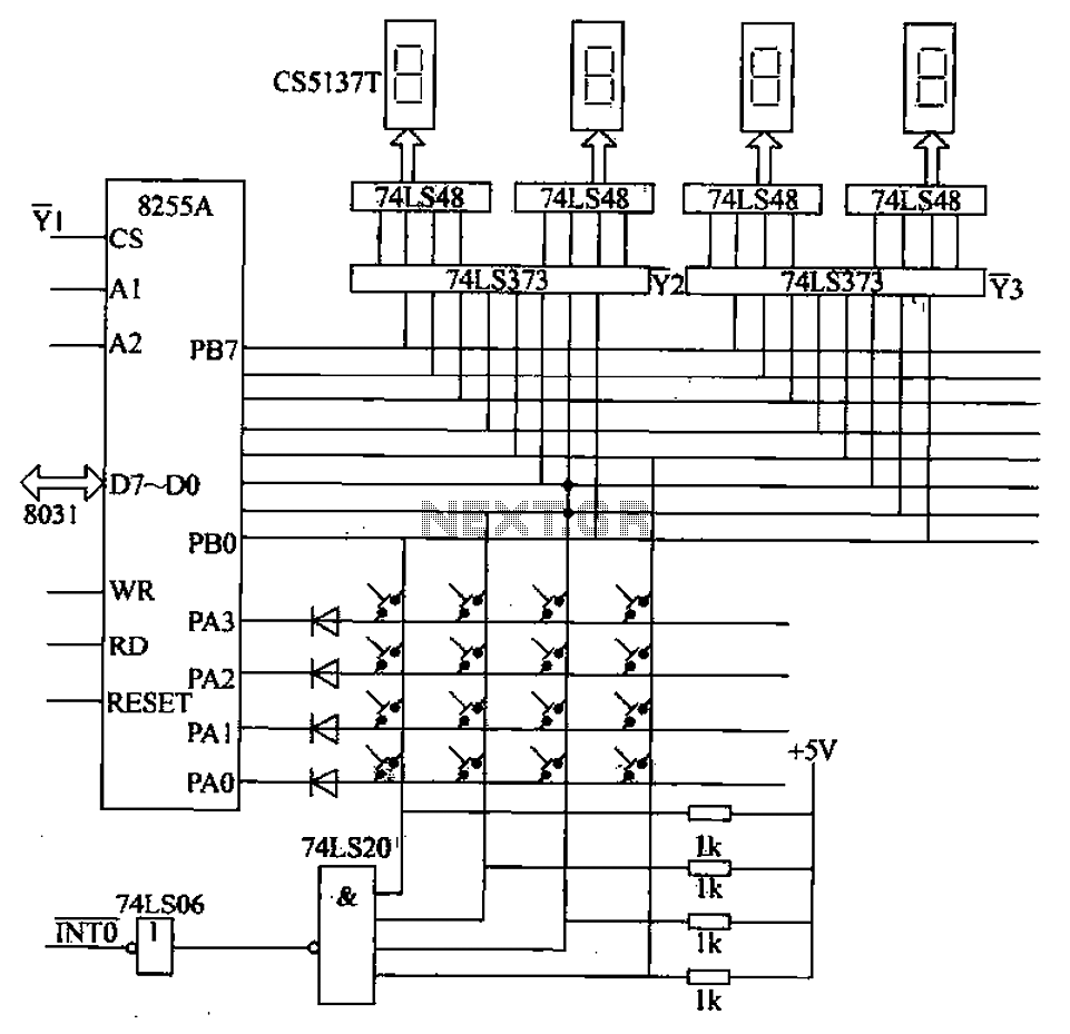
A 4x4 matrix keyboard system is designed for parameter settings, featuring numeric keys from 0 to 9 and function keys labeled A to F. The primary functions of the keyboard include completing parameter settings, selecting display modes, starting automatic...
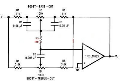
A simple tone control circuit can be designed using the LM833 operational amplifier along with a few external components. The LM833 is a dual general-purpose operational amplifier, specifically optimized for performance in audio applications. This tone control circuit utilizes...
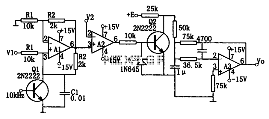
As illustrated in the dividing circuit diagram, A1 consists of a voltage-controlled current source, A2 functions as a voltage comparator, and A3 is configured as an active low-pass filter. When the time constant R1C1 is equal to the clock...
Warning: include(partials/cookie-banner.php): Failed to open stream: Permission denied in /var/www/html/nextgr/view-circuit.php on line 713
Warning: include(): Failed opening 'partials/cookie-banner.php' for inclusion (include_path='.:/usr/share/php') in /var/www/html/nextgr/view-circuit.php on line 713