
tone control circuit designed
The LM833 operational amplifier is well-suited for audio applications due to its low noise and high input impedance characteristics, which help maintain signal integrity. The tone control circuit operates by manipulating the frequency response of an audio signal, allowing users to boost or attenuate specific frequency ranges to achieve desired sound qualities.
The circuit consists of two primary components: the low-pass and high-pass filters. The low-pass filter allows frequencies below a certain cutoff frequency to pass through while attenuating higher frequencies. Conversely, the high-pass filter permits frequencies above a designated cutoff frequency to pass through while reducing lower frequencies. The interaction between these filters provides a means to adjust the tonal quality of the audio signal.
The cutoff frequencies for the filters can be calculated using standard RC filter formulas, which relate the resistance (R) and capacitance (C) values in the circuit to the desired frequency response. The specific values of resistors and capacitors used in the circuit will determine the exact cutoff frequencies. For instance, the low-pass filter cutoff frequency (fL) can be calculated using the formula fL = 1 / (2πRC), where R is the resistance and C is the capacitance. Similarly, the high-pass filter cutoff frequency (fH) is determined using the same formula, adjusting the configuration of the resistors and capacitors accordingly.
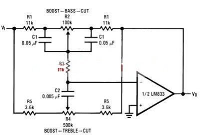
In summary, the LM833 tone control circuit is an effective solution for audio applications, providing users with the ability to finely tune their audio experience through the adjustment of specific frequency ranges. By selecting appropriate resistor and capacitor values, the circuit can be tailored to meet various audio requirements, making it a versatile tool for audio engineers and enthusiasts alike.Using LM833 can be designed a very simple tone control circuit using few external components. For this Lm833 ton control circuit can be used almost any type of operational amplifier if it have high input impedance. The LM833 is a is a dual general purpose operational amplifier designed with particular emphasis on performance in audio systems.
The ton control from this circuit is based on this operational amplifier from National Semiconductor and two RC filters ( low pass and high pass ). Using the formula presented bellow we can modify the frequency of the tone control circuit - the cut off frequency of RC filters (low pass and high pass )lm833 tone control formula For the tone control circuit presented in this schematic the frequencies are : fL = 32 Hz, fLB = 320 Hz and fH =11 kHz, fHB = 1.
1 kHz. 🔗 External reference
Related Circuits

A miniature real-time controller manages night lights, air conditioning units, and household appliances with a programmable scheduler. The device utilizes modified source code and a hex file for year 2002 readout. The circuit comprises three primary chips: an 89C2051...
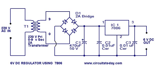
A simple 6-volt DC regulator circuit with a diagram and schematic using the 7806 IC, a positive voltage regulator. It serves as an elementary 6-volt, 1-ampere power supply circuit. The 7806 voltage regulator is a widely used integrated circuit that...
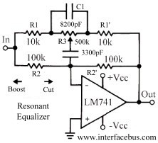
This topic discusses a resonant equalizer, which is a distinct type of circuit compared to the standard audio equalizer, although both achieve similar outcomes. The key difference is that the frequency responses of both the high and low frequency...
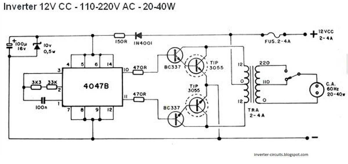
This schematic represents a simple 40W inverter that converts 12V to 220V. It has been functional for four years. The core component of the circuit is a CD4047 integrated circuit (IC) configured as an astable multivibrator. The resistance and...
This page shows some methods of track routing control for Stall-Motor type switch machines. The principle method uses a 2 Pole - Multi Position rotary switch while an alternate uses optoisolators and transistors to select the routes. The last...
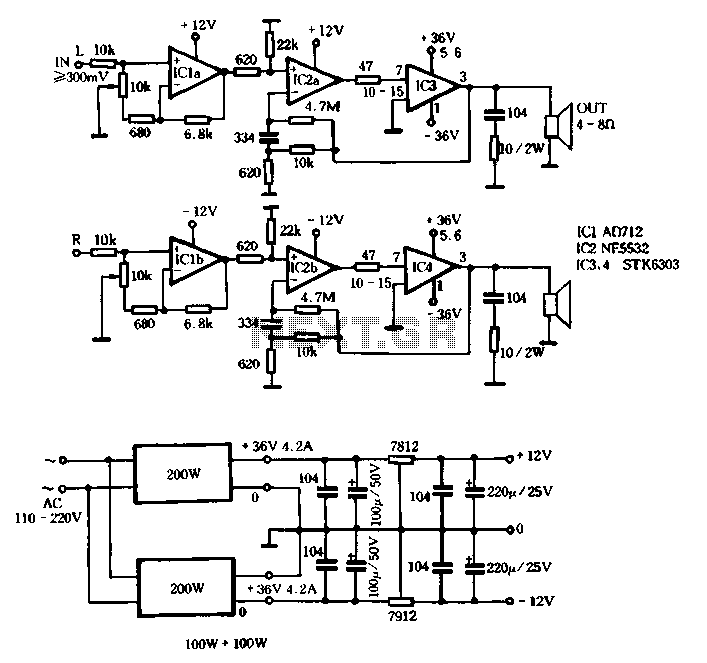
The T amplifier circuit schematic section is illustrated in Figure 3-51. It utilizes the Japan Sanyo STK6303 Pina, which is a high-power thick film integrated circuit. The maximum power supply voltage is 36V, and the output current can reach...
Warning: include(partials/cookie-banner.php): Failed to open stream: Permission denied in /var/www/html/nextgr/view-circuit.php on line 713
Warning: include(): Failed opening 'partials/cookie-banner.php' for inclusion (include_path='.:/usr/share/php') in /var/www/html/nextgr/view-circuit.php on line 713