
Autodyne Circuit
The Autodyne circuit exemplifies a compact and efficient design approach in RF receivers by consolidating multiple functions into a single transistor-based configuration. This integration not only simplifies the overall architecture but also enhances performance by reducing component count and potential signal degradation associated with inter-stage connections. The RF amplifier's role is crucial; it must be capable of low-noise amplification to maintain signal integrity before processing. The choice of a low-noise, high-gain transistor is essential as it directly influences the overall sensitivity of the receiver.
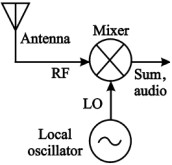
The mixing stage is pivotal in converting the amplified RF signal to an Intermediate Frequency (IF), which is easier to process. The use of a transistor or another active device in this stage allows for effective signal combination, leveraging the non-linear characteristics of the device to facilitate the mixing process. The output from the mixer then feeds into the IF stage, where further amplification and filtering occur.
The Local Oscillator generates a stable frequency that is critical for the mixing process. Its design must ensure that the output frequency aligns with the desired IF when combined with the incoming RF signal. The oscillator can take various forms, including the Hartley configuration mentioned, which is known for its simplicity and effectiveness in generating stable oscillations.
Feedback mechanisms within the oscillator can be adjusted to optimize performance, influencing parameters such as frequency stability and output amplitude. The arrangement of resistors for biasing the transistor is another vital aspect, as it determines the operating point of the circuit and affects gain and linearity. The flexibility in component choice and configuration allows for customization based on specific application requirements, including frequency ranges and performance criteria.
In summary, the Autodyne circuit represents an innovative approach to RF signal processing, effectively merging amplification, mixing, and oscillation into a singular design. This efficiency not only simplifies circuit design but also enhances performance, making it a valuable solution in various RF applications.An Autodyne circuit combines three functions normally found in different stages in an RF Receiver into a single circuit. However the three stages which are the RF amplifier, the Mixer and the Local Oscillator are normally found concatenated together.
Although each stage in a normal receiver would have an individual amplifier. In the case of an Aut odyne design, the RF amplifier, mixer and oscillator use the same transistor amplifier The RF amplifier stage is that portion of an RF receiver that receives a signal from the antenna and amplifies the signal so that it is usable by the following circuitry. In regards to this example the RF amplifier would have been a low-noise high-gain transistor amplifier circuit.
The Mixer Circuit would be attached, and follow the RF amplifier and use its own transistor [or other device] to combine the RF signal with the signal generated from the local oscillator. The mixer stage would then output its signal to the IF stage. The Local Oscillator circuit is designed to output a frequency that when mixed with the incoming RF will produce the correct Intermediate Frequency [IF] used by the rest of the circuit.
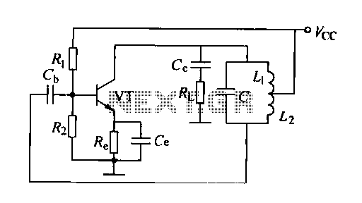
Normally the Local Oscillator [LO] is designed to function as a stand-along circuit. The Autodyne circuit shown above combines all three functions into a single design, using one transistor as both the amplifier and combiner. The circuit amplifiers the RF, functions as an oscillator and mixes the two signal together. The Autodyne schematic is just an example. The PNP transistor could just as well be an NPN type, a FET or any other amplifying component. In addition, the Common-Emitter circuit used is just one of three possible configurations for a transistor.
The style and type of oscillator could also take any form, this one appears to be a Hartley Oscillator. Also the methods of feed-back could be altered as shown on the Armstrong Oscillator page. Finally the resistors used to bias the circuit could change position, or bypass capacitors could be added.
No values are provided because they would have to change depending on the frequencies involved, the in coming RF, the LO frequency and so on. So in general the schematic is only meant to advance the definition of an Autodyne circuit, without going through the steps needed to design such a circuit.
Editor Comment: Use the dictionary links above or to the right to research any terms or functions used on the pages, or terms that might be related. Each dictionary is it`s own section, with individual links near the top of their pages. Many entries show additional graphics, or variations to different circuits. 🔗 External reference
Related Circuits
A feedback oscillator circuit utilizing inductance is presented, featuring the 3DG3 transistor. The component parameters reference values include: 1) transistors 3DG6, 2) resistances R1 at 91 kΩ, R2 at 11 kΩ, and R3 unspecified, 3) capacitance values of C...

This design outlines a high impedance DC voltmeter circuit utilizing the uA741 integrated circuit (IC). The uA741 is configured as a non-inverting DC amplifier. The circuit incorporates negative feedback through a DC meter that requires 1 mA for full-scale...

The duration for which the circuit remains active is determined by the time required for the stored electrical current to leak back into the circuit, which keeps the transistor and the entire circuit energized. A resistor is present that...
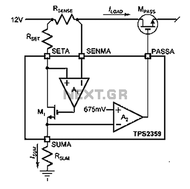
Amplifier A1 utilizes the voltage across the sense resistor sensors to monitor the load current ILOAD. The power management channel employs a similar circuit, with the distinction of integrating resistors RSENSE and RSET. Amplifier A1 is configured to measure the...
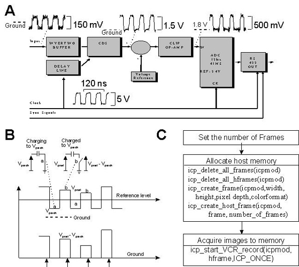
This document provides technical details regarding the hardware and software of a complete imaging system that utilizes a fast CCD sensor and a 41 Msample/s A/D converter. This system is capable of acquiring full-frame digitized images at a resolution...
Is the battery depleted, or is there an issue with the device? This question often arises when a battery-operated device, such as a Walkman, fails to power on. Before seeking professional repair services, it is advisable to first test...