
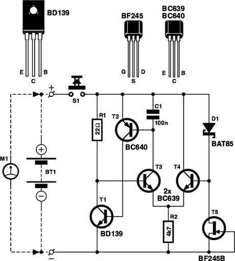
battery tester circuit schematic
A battery tester is an essential tool for diagnosing battery health and functionality in various electronic devices. The basic design of a battery tester typically includes a simple circuit that can measure voltage and, in some cases, load testing capabilities to assess the battery's performance under operational conditions.
The schematic for a basic battery tester may consist of the following components:
1. **Power Supply**: A small power source, such as a 9V battery, to power the tester circuit itself.
2. **Voltage Divider**: A resistor network that scales down the voltage of the battery being tested to a level that can be safely measured.
3. **Microcontroller or Analog Meter**: A microcontroller can be used to interpret the voltage readings and display them on an LCD screen, while a simpler analog meter can provide a direct voltage readout.
4. **Load Resistor**: This component is used to apply a known load to the battery, allowing for a more accurate assessment of its ability to deliver current.
5. **Switch**: A toggle switch to select between testing modes, such as voltage measurement and load testing.
6. **Output Display**: LEDs or an LCD screen to indicate the battery status, such as "Good," "Weak," or "Replace."
When constructing a battery tester, it is important to ensure that the components are rated appropriately for the maximum voltage and current that may be encountered. The circuit should be housed in a durable enclosure to protect it from physical damage and ensure longevity. Additionally, proper labeling and clear instructions should accompany the device to guide users in its operation.
In summary, a battery tester is a valuable tool that can save time and money by diagnosing battery issues before resorting to professional repair services. The design and construction of such a device can be straightforward, making it accessible for those with basic electronics knowledge.Is the battery empty, or is there something wrong with the device? That s always a difficult question when your walkman or some other battery-powered device appears to be dead when you switch it on. Before you take it to the shop for servicing, the first thing you should do is to test the battery or batteries.
Of course, this means you need a reliable battery tester, but it also means you can limit the damage to the cost of a battery or two and a one-time investment of time and money in building a suitable tester.. 🔗 External reference
Related Circuits
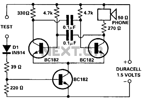
This tester is designed for tracing wiring on Printed Circuit Boards (PCBs). Resistors below 50 ohms function as a short circuit, while those above 100 ohms behave as an open circuit. The circuit comprises a simple multivibrator activated by...

An electronic rectification circuit that avoids the use of large, heavy, and expensive electrolytic capacitors by utilizing an active transistor in a gyrator configuration. To minimize excess ripple output on a power supply feeding a heavy load, a large...
This charger is based on a charging voltage of 2.4 volts per cell, in accordance with most manufacturers' recommendations. This circuit pulses the battery with 14.4 volts (6 cells x 2.4 volts per cell) at a rate of 120...
The main ΣΔ loop operates in steady state and is fully controlled by summing comparator Q2. This comparator amplifies the ripples of the sensed inductor current and output voltage with gains KI and KV, respectively, to generate an internal...
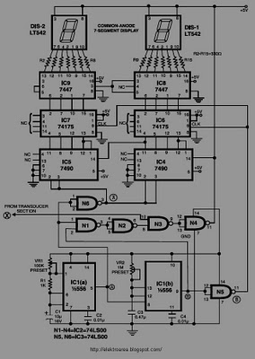
This circuit is designed to display the speed of a vehicle in kilometers per hour (km/h). An opaque disc is mounted on the spindle connected to the front wheel of the vehicle. The disc features evenly spaced holes along...
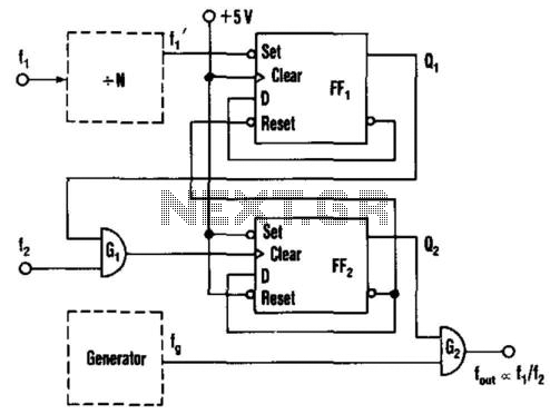
This circuit generates an output frequency that is linearly proportional to the ratio of two input frequencies. Each pulse of the bias frequency will open a switch for a period equal to half of the second input frequency, allowing...
Warning: include(partials/cookie-banner.php): Failed to open stream: Permission denied in /var/www/html/nextgr/view-circuit.php on line 713
Warning: include(): Failed opening 'partials/cookie-banner.php' for inclusion (include_path='.:/usr/share/php') in /var/www/html/nextgr/view-circuit.php on line 713