
Automated Attendant burglar alarm circuit
The automatic unattended burglar alarm circuit is designed for effective intrusion detection in various environments. The primary component, the pyroelectric infrared sensor, detects motion based on changes in infrared radiation, which is emitted by warm bodies, such as humans. The sensor's output is connected to an integrated circuit (IC1), which serves as the processing unit for the alarm system.
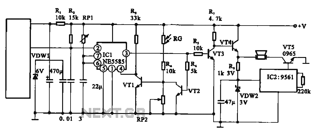
The light control circuit is critical to the operation of the alarm system, as it prevents false alarms during the day. The photoresistor RG is strategically placed to monitor ambient light levels. When the light intensity exceeds a certain threshold, RG's resistance drops, allowing current to flow through the base of transistor VT1, which subsequently turns on and short-circuits the alarm circuit, preventing it from activating during daylight hours.
At nighttime, the resistance of RG increases significantly, causing transistor VT1 to turn off. This transition prepares the circuit to enter an alert state. The pyroelectric infrared sensor remains vigilant, constantly monitoring for any movement within its detection range. If an intruder is detected, the sensor sends a signal to IC1, which activates the alarm driving circuit (IC2). This circuit typically includes a buzzer or siren, which emits a loud sound to deter the intruder and alert nearby individuals.
For optimal performance, the circuit may include additional components such as capacitors for filtering noise, diodes for reverse polarity protection, and possibly a power supply circuit to ensure stable operation. The overall design emphasizes reliability and ease of installation, making it suitable for both residential and commercial applications.It shows an automatic unattended burglar alarm circuit, mainly for family night, warehouses and other occasions automatic unattended. The circuit consists of pyroelectric infrared sensor light control circuit (RG, RP2, R4), the alarm driving circuit (IC2 and foreign components) , and the like. At higher light intensity during the day, low resistance state photoresistor RG, the transistor is turned on VTI, the alarm circuit shorted: In the night -RG resistance value becomes larger, VT1 off, ready to enter the stage alarm circuit alarm state, when someone enters the pyroelectric infrared sensor probe measured area, ICI foot is triggered, the buzzer alarm.
Related Circuits
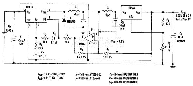
Large input-to-output voltage differentials, caused by wide input voltage variations, reduce a linear regulator's efficiency and increase its power dissipation. A switching preregulator can reduce this power dissipation by minimizing the voltage drop across an adjustable linear regulator to...
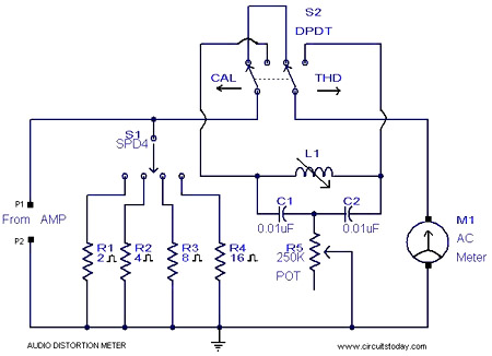
This is a simple 1 kHz audio distortion meter designed to measure the Total Harmonic Distortion (THD) on any load at any output power. The circuit allows for the selection of load impedances of 2, 4, 8, or 16...
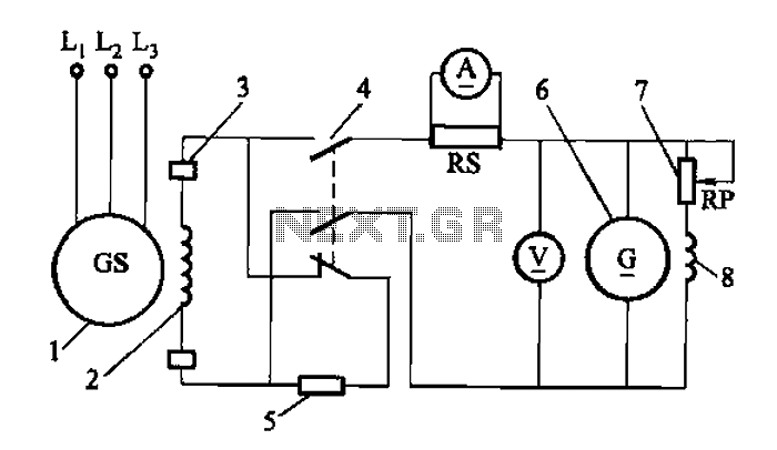
Adjust the exciter field rheostat RP to change the exciter output voltage, which in turn adjusts the generator excitation current, allowing for modifications to the generator output voltage for various purposes. The exciter field rheostat (RP) is a critical...
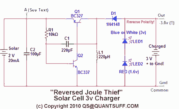
This design presents an innovative approach to the Joule Thief (JT) circuit typically utilized in garden lights. Instead of directly charging a 1.2V battery from the solar cell and converting the power to operate a 3-volt LED, this circuit...

This article discusses a simple 5-channel radio remote control circuit utilizing the TX-2B and RX-2B integrated circuits from Silan Semiconductors. The TX-2B/RX-2B is a remote encoder-decoder pair suitable for remote control applications. It features five channels, a wide operating...
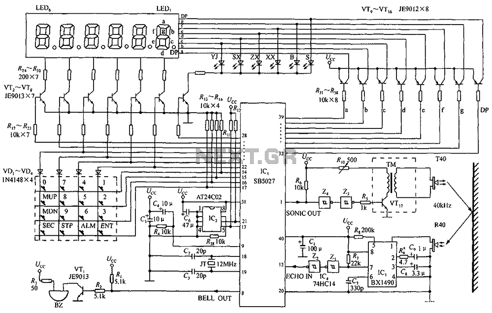
A circuit diagram of an ultrasonic range finder is constructed using a clock with a calendar and the Ultrasonic Ranging IC SB5027. The ultrasonic range finder circuit utilizes the Ultrasonic Ranging IC SB5027, which is designed to measure distances by...
Warning: include(partials/cookie-banner.php): Failed to open stream: Permission denied in /var/www/html/nextgr/view-circuit.php on line 713
Warning: include(): Failed opening 'partials/cookie-banner.php' for inclusion (include_path='.:/usr/share/php') in /var/www/html/nextgr/view-circuit.php on line 713