
By a clock with a calendar Ultrasonic Ranging IC SB5027 a circuit diagram of an ultrasonic range finder
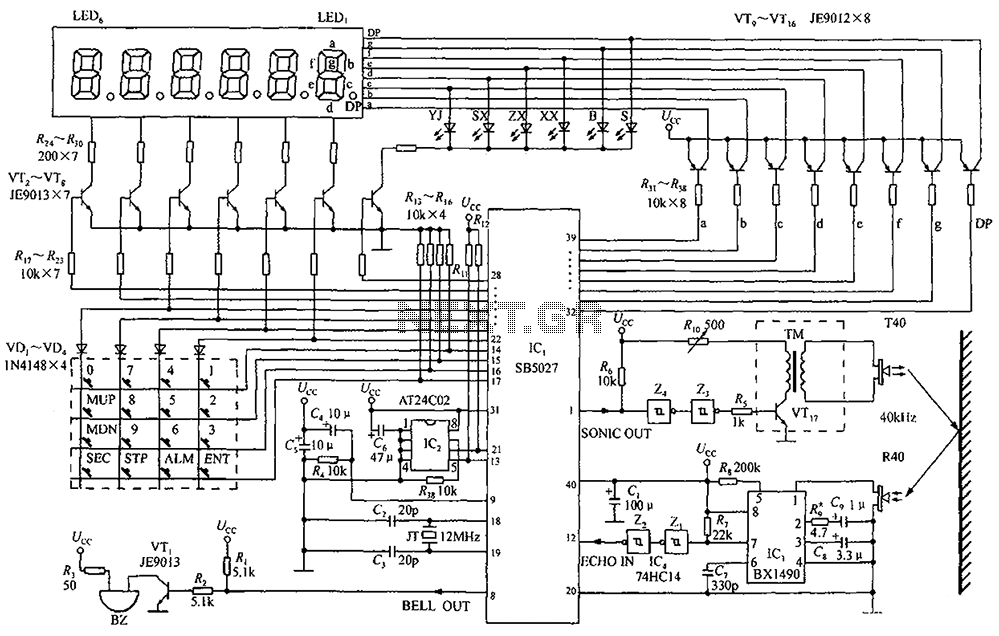
The ultrasonic range finder circuit utilizes the Ultrasonic Ranging IC SB5027, which is designed to measure distances by emitting ultrasonic waves and calculating the time taken for the waves to return after reflecting off an object. This IC integrates various functionalities, including a clock with a calendar, which can be employed to timestamp measurements or synchronize operations.
The circuit typically includes a transmitter and receiver pair, where the transmitter emits ultrasonic pulses at a specific frequency. The SB5027 manages the timing of these emissions and listens for the echoes. Upon receiving the reflected signal, the IC calculates the distance based on the speed of sound in air, utilizing the time delay between emission and reception.
Additional components in the circuit may include a microcontroller for processing the distance data, a display module for visual output, and various passive components such as resistors and capacitors to ensure stable operation. The microcontroller can be programmed to trigger measurements at regular intervals, utilizing the calendar feature to log data over time, which can be useful for applications requiring historical distance tracking.
Power supply considerations are also critical in the design, as the circuit should operate efficiently within the specified voltage range of the SB5027. The layout should minimize interference and optimize the positioning of the transmitter and receiver for accurate measurements. Overall, this ultrasonic range finder circuit is a versatile tool for various applications, including automation, robotics, and obstacle detection. By a clock with a calendar Ultrasonic Ranging IC SB5027 constitute a circuit diagram of an ultrasonic range finder
Related Circuits
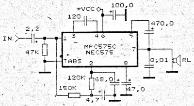
An amplifier circuit is particularly well-suited for use in confined spaces, such as within vehicles. It requires a voltage supply ranging from 9 Volts to a maximum of 17 Volts. This amplifier circuit utilizes the IC MPC575C, which is...
This simple charger utilizes a single transistor as a constant current source. The voltage across the pair of 1N4148 diodes biases the base of the BD140 medium power transistor. The circuit operates by employing the BD140 transistor to regulate the charging...
The circuit on this page is for a simple light detector circuit board that has 8 detectors that can be used with visible or infrared light systems. The detectors use LM339 voltage comparators as the active element. Phototransistors or...

Driving a D/A converter using an A/D converter provides an overall analog-hold function. Although this function has limitations in output resolution, it offers zero voltage droop and infinite hold time. The A/D converter depicted (IC1) features a 12-bit compatible...
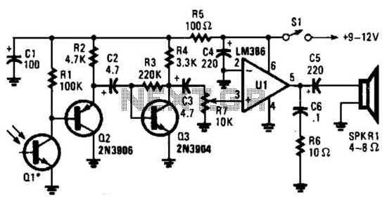
This receiver for amplitude-modulated light signals utilizes a phototransistor Q1 mounted within a parabolic reflector to enhance its range. Any NPN phototransistor is suitable for this application. An emitter-follower configuration using Q2 drives an amplifier stage Q3. The output...
The LED flasher circuits operate on a single 1.5-volt battery. The circuit on the upper right utilizes the popular LM3909 LED flasher IC and requires only a timing capacitor and an LED. The LED flasher circuit using the LM3909 integrated...