
Automated Water Tank Filler
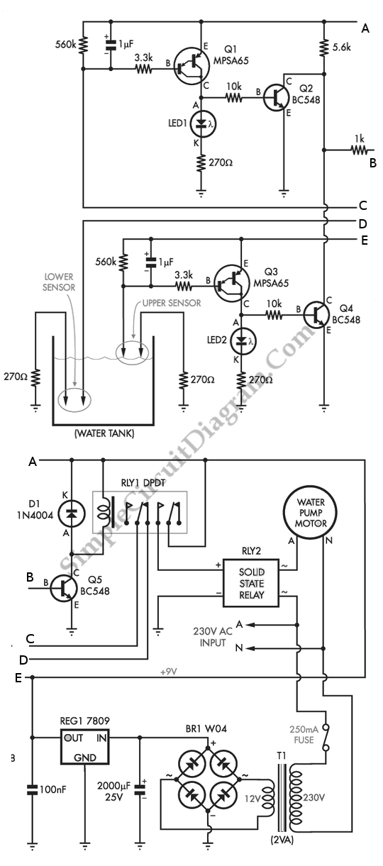
The proposed circuit operates by continuously monitoring the water level in the header tank and controlling the operation of the submersible bore pump accordingly. The system typically includes water level sensors, such as float switches or pressure transducers, that detect the water level at predetermined points.
When the water level falls below a set threshold, the sensor activates the pump, allowing water to fill the tank until the upper threshold is reached. Conversely, if the water level exceeds the upper limit, the circuit will deactivate the pump to prevent overflow.
Key components of this circuit may include a microcontroller or relay system to process the signals from the sensors and control the pump operation. Additionally, protective devices such as circuit breakers or fuses can be integrated to safeguard against electrical faults.
The design should also consider the power supply requirements for the pump and control circuitry, ensuring that appropriate voltage and current ratings are maintained. Adequate wiring and connectors must be selected to handle the load of the 3HP pump, which may require specific gauge wiring to prevent overheating and voltage drops.
In summary, this circuit is essential for automated water level control in a header tank system, providing efficient operation of the submersible bore pump while ensuring that water levels remain within safe and functional limits.We can use the circuit below to maintain the level of water in the header tank within prescribed limits. A 3HP submersible bore pump which has a high starting.. 🔗 External reference
Related Circuits
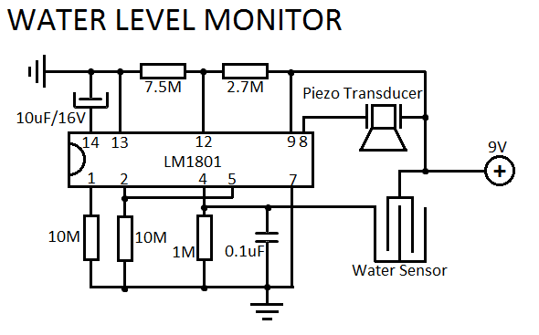
This simple water level sensor circuit monitors the presence of water in a specific location or container. The circuit activates an acoustic alarm when it detects water. The water level sensor circuit typically consists of several key components, including a...
An annual listing of the watermelon season reveals that many individuals lack the intuitive judgment to differentiate between raw and cooked watermelon. This often leads to unnecessary disputes regarding the classification of the fruit. A proposed solution is the...
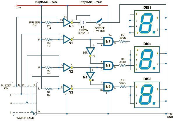
This schematic outlines a straightforward electronic project for designing a water level indicator circuit. It employs a 7-segment display to represent water levels in a tank as low, half, and full, indicated by the letters L, H, and F,...
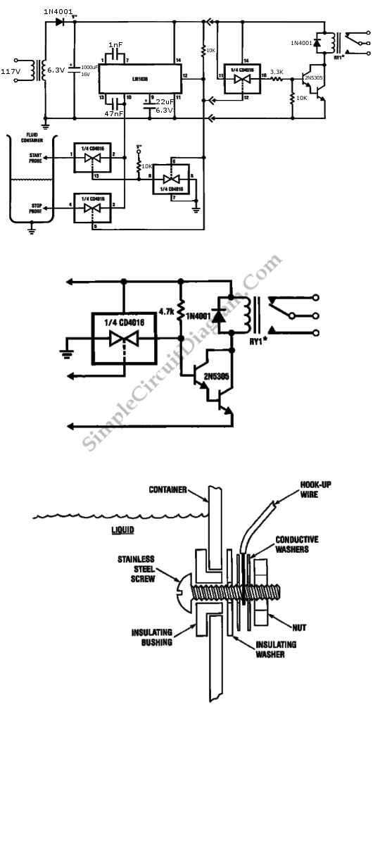
This is a fluid, liquid, or water level control circuit utilizing the LM830. The LM830 is capable of detecting the presence and absence of aqueous fluids. This application employs two... The fluid level control circuit based on the LM830 is...
This circuit is designed to indicate when a plant requires watering. An LED blinks at a low frequency when the soil in the flower pot is excessively dry, turning off as the moisture level rises. The sensitivity of the...
That circuit is based at a technique to remove or neutralize the salt in water, and protect the pipes at home as well as the washing machines or our selves from salt. Its called water softener and its automated...