
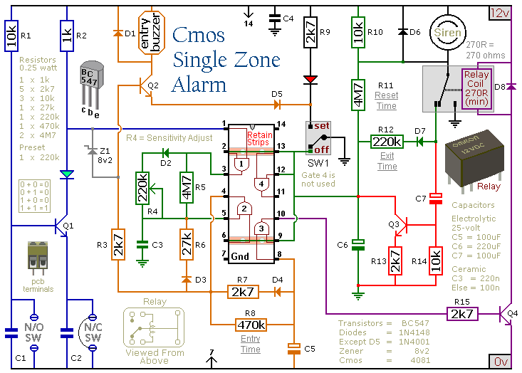
Automatic Arming Auto Alarm

The described circuit utilizes a 555 timer IC to manage timing functions for both the exit and entry delays. When the vehicle is turned off, Q2, a switching transistor, is responsible for redirecting the power supply to the timing circuit (U1). The operation of U1 is crucial, as it determines how long the user has to exit the vehicle before the system arms itself. The activation of Q3 ensures that power to U2 is cut off during the vehicle's operation, thus preventing false alarms.
LED indicators serve as visual cues for the system's status—disarmed and armed—allowing users to easily ascertain whether the alarm is active. The cascading timer configuration within U2 allows for a flexible response based on user actions, such as opening or closing car doors, which can retrigger the alarm sequence, thereby enhancing security.
The alarm itself is controlled by Q5, which is activated by the output of the second stage of U2. This design ensures that the alarm can sound for a specific duration, providing an alert for unauthorized access. The system is reset automatically after the alarm duration, ensuring that it is ready for the next potential trigger.
Incorporating a manual override switch at J3 provides added convenience, allowing users to disable the alarm without dismantling the entire system, particularly useful during maintenance. The design also includes a security feature within switch S1, which prevents tampering with the alarm system, ensuring that any attempt to remove the unit will result in a triggered alarm, thereby enhancing vehicle security. The circuit automatically turns on when the car is turned off. It gives you a variable time to get out and lock up, and also provides a variable time delay to get in and start the car. The 555 oscillator/timers are always powered down when the car is on. That keeps the alarm from going off while you"re driving. As soon as the car is turned off, Q2 switches off and shunts power to Ul. When that happens, Ul immediately sends its output high, keeping Q3 on, and thereby prevents power from returning to U2. Transistor Q2 also sends power to Q3"s collector to be used only when Ul has completed its timing cycle.
When Ul has finished, it turns Q3 off, which in turn activates Q4, and sends power to the balance of the circuit. That timing period was the time needed to get out of the car. LED1 indicates that the system is disarmed and LED2 indicates that the system is armed. At this point, U2 waits for a trigger pulse from the car"s door switches or dome light. A positive impulse at the 401 l"s input sends a negative trigger pulse to the first stages of U2, which is connected as a cascading timer.
The first stage"s output becomes high for a time to allow the car to be turned on. If that does not happen, the first stage"s output lowers, which sends a low trigger pulse to the second stage. The second stage then sends its output high, turning on Q5, which sounds the alarm for a given time. Once that time has elapsed, the alarm is shut off by a low output to Q5 and the system is reset. If the car door is closed or a second door opened while the alarm is sounding, the first stage retriggers and prepares to extend the ON-time of the alarm.
The cascading or counting action continues until the car is left alone. You can add a switch on the positive supply rail at J3 to override and silence the alarm, if (for example) you plan to work on the car. Switch SI is a normally closed type that is built into the case of the alarm; SI is pushed to the open position when the case is mounted flush with a surface.
Any attempt to remove the alarm will sound the alarm. 🔗 External reference
Related Circuits
This circuit utilizing a 555 timer IC can be used as an alarm system to prevent the theft of your luggage, burglars breaking into your house, etc. The alarm goes ON when a thin wire, usually as thin as...
This circuit includes automatic exit and entry delays, a timed bell cut-off, and a system reset feature. It is designed to support both normally-open and normally-closed switches and can accommodate standard input devices such as pressure mats, magnetic reed...
An ultra-simple circuit of the tilt sensor alarm can be fabricated using readily available, inexpensive components. The circuit operates as a true transistor-based design. The tilt sensor alarm circuit utilizes a tilt sensor, which is a device that detects the...
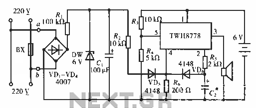
The circuit functions as an AC blown fuse alarm. When the fuse (BX) is intact, 220 V AC voltage passes through a bridge rectifier composed of diodes VD1 to VD4. Resistor R1 limits the current, and the output is...
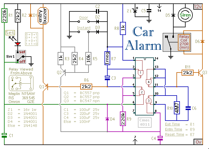
This car alarm circuit includes exit and entry delays, an instant alarm zone, an intermittent siren output, and automatic reset. By incorporating external relays, it is possible to immobilize the vehicle and activate the flashing lights. The car alarm circuit...

Composition ratio circuit. The circuit consists of resistors and capacitors that form a shift register circuit with diodes VD1 to VD4, creating a bridge for electric current. Capacitor C4 is utilized for filtering applications and for eliminating instantaneous relay...