
Automatic audio fader circuit
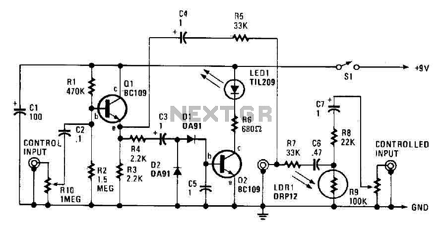
The automatic fader circuit is designed to dynamically adjust the audio levels by reducing the volume of background music when narration occurs, ensuring clarity and intelligibility of the spoken content. The control input, provided through RIO, allows for preset audio levels to be established, facilitating consistent performance in varying audio environments.
The emitter-follower buffer stage (Q1) is crucial for maintaining high input impedance, allowing the circuit to interface effectively with various audio sources without loading them down. This buffer stage also ensures that the rectifier and smoothing circuit, comprising diodes D1 and D2 along with capacitor C5, receive a low enough source impedance to function correctly. The rectified and smoothed output is then utilized to drive an LED (LD), which visually indicates the status of the circuit.
The infrared input pad, formed by the LED (LD) and resistor R8, plays a significant role in the circuit's operation by detecting the presence of an input signal. The output is then filtered through capacitors C6 and C7 before reaching the output jack, ensuring that only the desired audio signal is passed on.
The coupling of the output to the emitter of Q1 through capacitors C4 and R5 allows for effective signal mixing. Resistors R5 and R7 function as a passive mixer, enabling the combination of multiple audio signals. The circuit is designed to respond to input levels, activating transistor Q2 when the input voltage surpasses 200 mV. This activation energizes the LED, providing a visual cue that the background music is being attenuated. The use of a light-dependent resistor (LDR) further enhances the circuit's functionality; as the resistance of the LDR decreases, it contributes to increased attenuation of the background music, thereby improving the prominence of the narration.
At higher input levels, such as 350 mV RMS, the circuit is capable of achieving significant signal reduction, exceeding 20 dB. This level of attenuation ensures that the narration remains clear and distinct, effectively managing audio levels in real-time and enhancing the overall listening experience.The automatic fader drops at the background music while the narration is in place. The control input through RIO, a preset audio level control, into an emitter-follower buffer stage CQI). The buffer provides high input impedance and ensures that the source impedance is low enough to drive the rectifier and smoothing circuit, consisting of DI, D2, and C5.
The smoothed output drives a simple LED circuit. LD and R8 form an IR input pad through which the output is fed through C6 and C7 to the output jack. The output to the emitter of QI couples making this C4 and R5. R5 and R7 are a passive mixer. With 200 mV or less at the entrance, there is enough voltage on C5 to tum Q2. More than 200 mV, Q2 will turn on a boundary, and the LED is energized. This brings down the resistance of the LDR, and signal loss due to increased attenuation. Increase the input of 350 mV rms, and you get a signal reduction greater than 20 dB. 🔗 External reference
Related Circuits
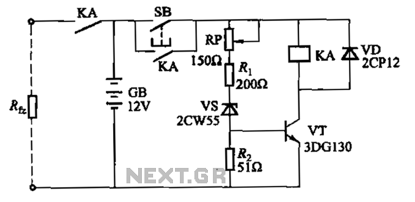
Deep discharge of a battery can lead to plate curing, which shortens the battery's lifespan. To prevent this, a discharge protection device can be implemented. The circuit diagram illustrates this mechanism. When the battery voltage falls to a predetermined...
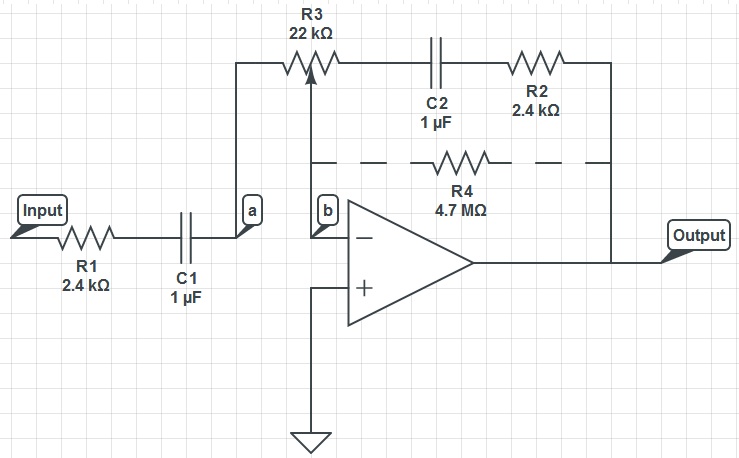
This circuit can function as a treble control circuit, with high-frequency gain occurring when resistor R3 is set to a value that makes points a and b equal (denoted as k=0). Conversely, high-frequency attenuation occurs when R3 is set...
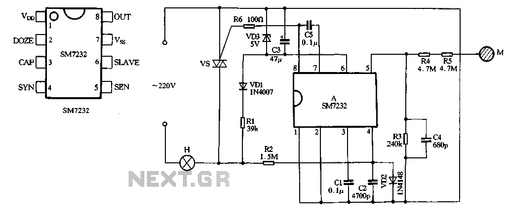
The core component of the circuit is the dimmer, utilizing the SM7232 integrated circuit. The pin configuration includes: 1) VDD, the positive power supply terminal; 2) DOZE; 3) CAP; 4) SYN, which synchronizes input power frequency using an internal...
Two working examples have been assembled, one utilizing a PNP and an NPN transistor, and the other employing two MOSFETs. Both circuits function correctly, but as anticipated, the MOSFET circuit draws significantly less current (0.1 mA compared to 4.5...

This circuit diagram represents a low-cost metal detector utilizing a single transistor circuit in conjunction with an old pocket radio. It operates as a Colpitts oscillator functioning within the medium band frequency range, with the radio tuned to the...
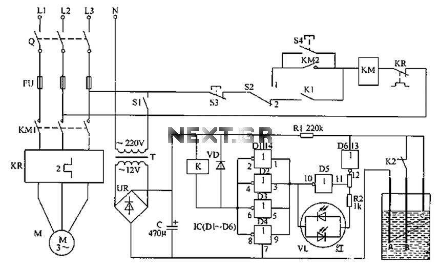
The liquid level automatic controller circuit consists of a power circuit, a control instruction level detection circuit, and a starter control circuit. The power circuit is formed by a power transformer, a rectifier bridge, and a filter capacitor. The...