
amplifier How does this circuit attenuate high frequencies

The feedback mechanism in this circuit is crucial for understanding its operation. Capacitor C2 consistently presents a lower impedance at high frequencies, suggesting that adjusting R3 should primarily influence the gain at these frequencies. The role of feedback in amplifiers is essential, particularly in maintaining stability and controlling voltage fluctuations between the virtual ground input nodes. The circuit utilizes DC feedback to counteract any variations in voltage at the inputs by outputting a signal with a DC offset that is opposite to that at the inputs. While AC feedback can pass through a capacitor, it behaves like an open circuit for DC signals.
This circuit can be designed with the following components and configurations:
1. **Resistors**: R3 is the variable resistor that determines the circuit's behavior as either a high-pass or low-pass filter. The resistance value is critical, as it dictates the frequency response of the circuit.
2. **Capacitor**: C2 is a capacitor that influences the impedance characteristics of the circuit. Its lower impedance at higher frequencies allows for the desired filtering action.
3. **Amplifier**: An operational amplifier (op-amp) can be used to amplify the signal. The configuration of the feedback loop (including the resistors and capacitor) around the op-amp is essential for achieving the desired frequency response.
4. **Power Supply**: The circuit requires a stable DC power supply to operate the op-amp, ensuring consistent performance.
The circuit's performance can be analyzed using Bode plots to visualize the gain and phase shift across different frequencies. The transition between the high-pass and low-pass behavior is determined by the cutoff frequency, which can be calculated based on the values of R3 and C2.
In summary, this treble control circuit exemplifies the principles of feedback in amplifiers and the significance of component values in determining the overall frequency response. Proper understanding of these elements is crucial for effectively utilizing and modifying the circuit for various audio applications.This circuit could be used as a treble control circuit with high frequency gain occuring when R3 is set so a=b (we`ll call this k=0), and high frequency attenuation occuring when R3 is 22kOhms across a and b (k=1). So therefore, depending on R3`s setting, this circuit is either a high pass (k=0) or low pass (k=1) filter.
When comparing this circuit to high and low pass filters, I do not understand what is happening: C2 will always have a lower impedance for high frequencies and so surely adjusting R3 will only alter positive gain for high frequencies. It`s not a duplicate, but you are trying to understand this circuit without having clear what the simgle parts do.
Did you understand how the feedback works for an amplifier clabacchio™ May 16 `12 at 9:44 @clabacchio Yes, I think so. I understand that DC feedback is needed to control any fluctuations in voltage between the virtual ground input nodes to the amplifier.
It does this by outputing the signal with a DC offset opposite to that at the inputs. Although AC feedback can travel over a capacitor, for any DC signal it acts like an open circuit. user1083734 May 16 `12 at 9:50 I am a beginner but am finding all of the answers I have recieved on electronics. I realise the power of this resourse and certainly do not want to waste anybody`s time user1083734 May 16 `12 at 9:52 It`s not about that: you have to understand that DC feedback and AC feedback are, in principle, feedbacks.
From your first comment I see some confusion, and I don`t blame you :) but you should take things a bit more step by step. I`ve also edited my answer to give a bit more general notions, check it. clabacchio™ May 16 `12 at 10:00 🔗 External reference
Related Circuits
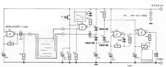
The circuit diagram is straightforward and operates as follows: the N1 Schmitt trigger functions as an oscillator, producing a frequency of approximately 1 kHz. When there is sufficient water in the tank, alternating voltage flows from electrode A to...
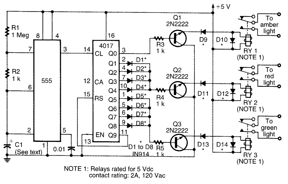
This circuit utilizes a 555 timer to control a 4017 decade counter. The outputs from the counter are used to drive transistor relay drivers. The duration for which the lights remain "on" can be adjusted by modifying the connections...
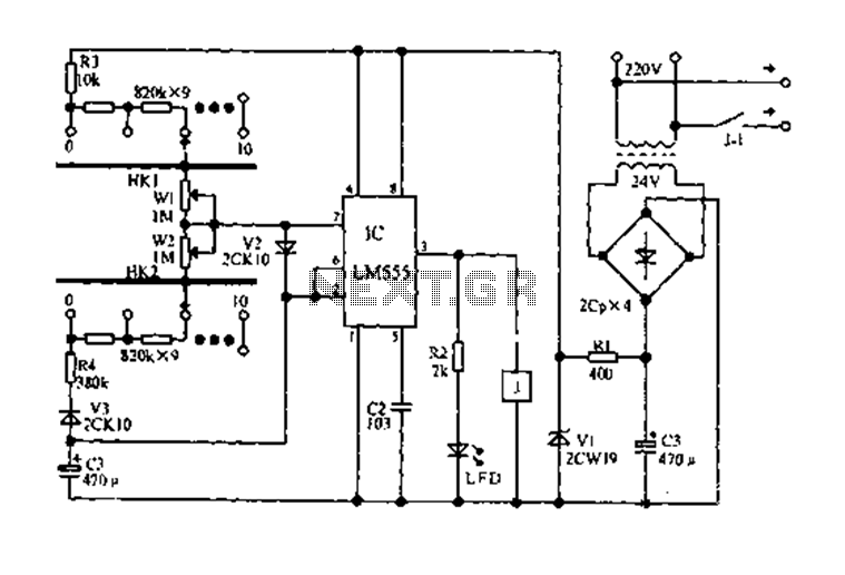
The circuit diagram for an electric start and stop timer is illustrated in the following cycle. It utilizes the LM555 integrated circuit configured as an adjustable duty cycle multivibrator. The circuit includes components C3, KH1, W1, KH2, and W2,...
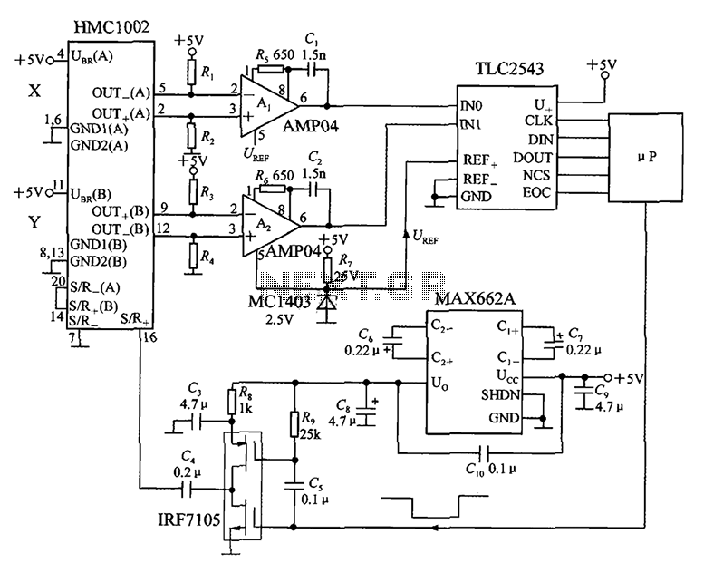
An application circuit for a biaxial magnetic field sensor is presented. This circuit utilizes the HMC1002 biaxial magnetic sensor along with two AMP04 amplifiers (A1, A2) to simultaneously measure magnetic fields in both the X-axis and Y-axis directions. The...
LCD modules have become a popular means of displaying system messages and status in embedded applications. This application note demonstrates how to interface an SST FlashFlex microcontroller to a typical character LCD module. The SST FlashFlex is an industry-standard,...
A balanced diode mixer circuit is presented, utilizing two diodes, specifically the 2AP9 model. The circuit operates with a high voltage, causing the diodes to function in an off state, which is also referred to as a diode switch...