
Automatic level control circuit diagram of the four
The liquid level automatic controller circuit is designed to maintain a specific liquid level within a reservoir by utilizing a combination of electronic components and control logic. The power circuit begins with a transformer that steps down the AC voltage from the mains to a lower voltage. This lower voltage is then rectified by a bridge rectifier, which converts the AC to DC, and filtered by a capacitor to provide a stable DC supply for the control circuits.
The level detection circuit employs electrodes that sense the liquid level within the reservoir. Electrode 'b' acts as the low-level sensor, while electrode 'c' serves as the high-level sensor. When the liquid level rises above electrode 'b', the output of the corresponding non-gate IC changes states, triggering a series of actions. Specifically, when the reservoir level is above electrode 'b', the relay does not activate, keeping the pump motor off and illuminating a green LED to indicate that the liquid level is adequate.
Conversely, when the liquid level drops below electrode 'b', the circuit activates the pump motor to refill the reservoir. This is indicated by the red LED turning on. The relay engages, closing its normally open contact to power the AC contactor, which in turn energizes the pump motor. The system is designed to stop the pump when the liquid reaches electrode 'c', ensuring that the reservoir does not overflow.
For manual operation, a switch allows the user to bypass the automatic control, enabling continuous operation of the pump motor until the stop button is pressed. The thermal relay provides an essential safety feature, disconnecting power to the pump motor in the event of an overcurrent condition, thus preventing damage to the system.
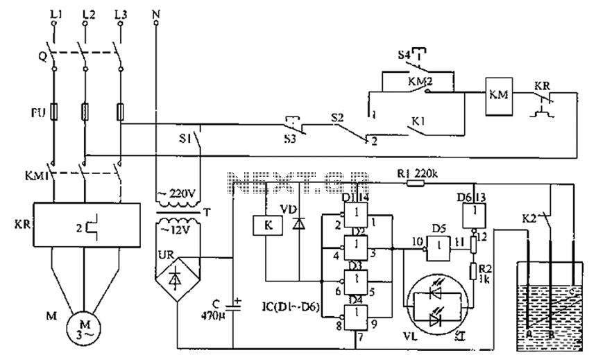
Component specifications are critical for ensuring reliable operation. Resistors R1 and R2 are typically rated at 1/4W, while the filter capacitor is a 25V aluminum electrolytic type. The color LED is chosen for its visibility, and the non-gate integrated circuits are selected for their compatibility with the circuit's logic requirements. The relay must be capable of handling the load associated with the pump motor, and the electrodes can be made from conductive materials such as stainless steel or brass to ensure accurate level detection. Overall, this circuit is a robust solution for automatic liquid level control in various applications. Circuit works The liquid level automatic controller circuit from the power circuit, control instruction level detection circuit, the starter control circuit, as shown in FIG. F IG automatic level control circuit Power circuit from the power transformer T, rectifier bridge pile and filter capacitor C form. Level detection control circuit by the level sensing electrode indicating a ~ c, six non-gate IC IC (D1 ~ D6), resistors R1, R2, relay K, color LED VL and diode VD composition.
Starter control circuit knife switch Q, fuses FU1 ~ FU3, power switch 5S1, manual/automatic control switch S2, the stop button S3, the start button S4, AC contactor KM and thermal relay KR composition. AC 220V voltage by T Buck, UR rectifier and C filter for liquid level detection and control/display circuit provides 12V DC voltage.
Electrode is a common electrode (ground electrode), an electrode is low level electrode b, c high level electrode electrode. When the reservoir pool level is higher than the electrode b, D6 because the input terminal is low and output high, D5 output low, VL emits green light (its internal green LED lights), D1 ~ D4 are high output, relay K does not pull its normally closed contact connected, normally open contact K1 disconnect, AC contactor KM does not pull, plus pump motor M does not work.
When the reservoir pool level dropped to less electrode b, D6 output low, D5 output high, D1 ~ D4 output low level VL emits red light (its internal red LED lights), while K pull power, the normally closed contacts disconnect normally open contact connected, KM pull its normally open contact connected, so M power work, plus sump pump began to add liquid. When the liquid level rises to the pool when the electrode c, D6 and D1 ~ D4 and output high, K and KM release, M to stop working.
When the level drops electrode c or less, due to the K2 contact connected, D6 output is still high, M still does not work, only when the level falls electrode b or less, M is energized to work. Again and again, so that the reservoir pool level is maintained between the electrode and the electrode b c.
When the need to manually control the S2 placed in the manual position, press the start button and overcast. It can make the pump motor M plus continuous work. When you need to stop the liquid supply, click the stop button S3 can. If the increase in pump motor M for some reason there is overcurrent, the thermal relay KR will be immediate action, the normally closed contact is open, make KM release, M is the power supply cut off.
Component selection R1 and R2 use 1/4W carbon film resistors or metal film resistors. C selected voltage is 25V aluminum electrolytic capacitors. VL choose 2EF302 type color light-emitting diodes. IC selects CD4069 or C033, CH4069, CC4069 type six non-gate integrated circuits. K selection JRX-13022 type 12V DC relay. T chooses 3W, voltage of 12V power transformer. S1 and S2 are selected contact current load is greater than the control switch. 5A. Q, FU, KM, KR and S3, S4 can be added according to the pump motor power to choose. Electrode can be a ~ c stainless steel pipe (or wire), aluminum alloy or brass pipes and other production.
Related Circuits
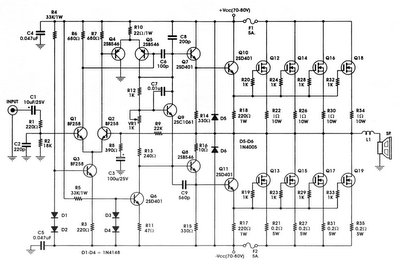
The circuit incorporates components Q, C, and ZD, which are responsible for the bias and buffer stages. Its primary objective is to ensure stable MOSFET gate operation and provide an offset voltage through a voltage buffer amplifier stage with...
A simple thermostat circuit can be utilized to control a relay, which in turn supplies power to a small space heater via the relay contacts. It is essential that the relay contacts are rated above the current requirements for...
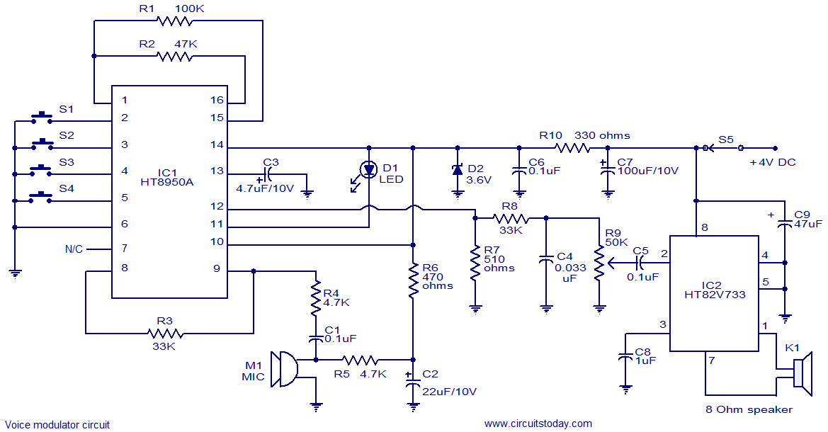
This is a versatile voice modulator circuit utilizing the HT8950A IC from Holtek Semiconductors. The IC can generate seven upward or downward frequency steps based on the input voice at a rate of 8 Hz. Additionally, it features two...
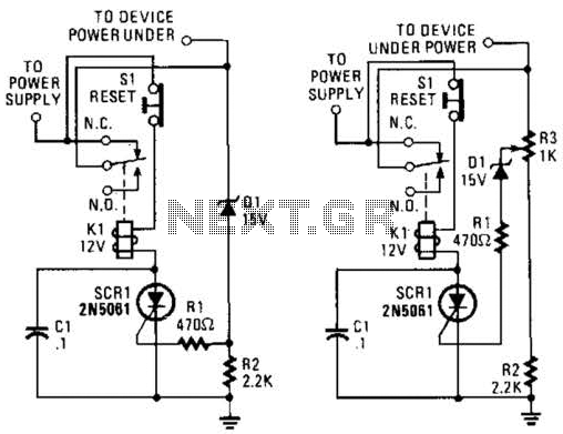
If circuits experience frequency overvoltage conditions, continually replacing blown fuses can become quite costly. This shutdown circuit addresses that issue by substituting the fuse with a relay and a low-current SCR. When the input voltage exceeds the threshold established...
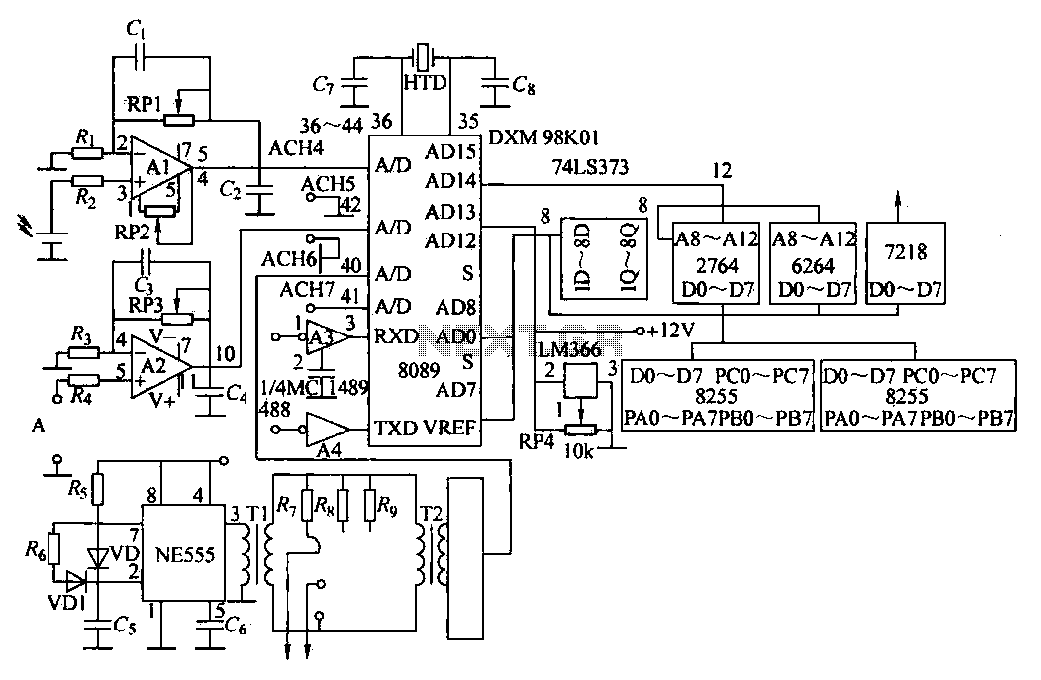
Direct measurement circuit for soil content, assessing various parameters such as moisture, salinity, nitrogen, and pH to enhance soil quality for diverse agricultural crops. This electronic measuring circuit facilitates rapid and accurate testing of soil conditions and informs fertilization...
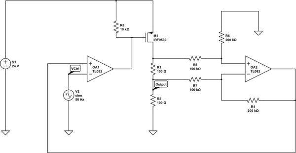
Create a 0-25 mA current limiter using a control voltage input of 0-5 V to regulate the current through a resistive load (R2), which can vary between 0-200 ohms. The O2 operational amplifier (op-amp) functions as a differential amplifier...