
Timer with alarm circuit
The 4060 integrated circuit (IC) serves as the core component of this alarm timer circuit. It combines a high-stability oscillator with a binary counter, making it suitable for timing applications. The oscillator's frequency can be adjusted by selecting appropriate external resistors and capacitors connected to the IC. This flexibility allows the user to set the desired time interval for the alarm function.
The circuit typically operates in the following manner: when powered, the 4060 generates a clock signal at its output pin, which is then fed into a series of flip-flops that divide the frequency. The output from these flip-flops can be configured to trigger an alarm or indicator when the count reaches a predetermined value.
An additional feature of the circuit may include a reset mechanism, which can be implemented using a push-button switch. This allows the user to reset the timer and start the counting process anew. The output can be connected to various types of alarms, such as a buzzer or LED, to signal when the timer has elapsed.
To ensure proper operation, it is essential to provide the correct power supply voltage to the 4060 IC, typically in the range of 3V to 15V, depending on the specific variant used. The design can be further enhanced by incorporating a power-saving feature, such as a low-power mode, which can be activated when the timer is not in use.
In summary, this simple alarm timer circuit utilizing the 4060 IC provides a reliable and adjustable timing solution, suitable for various applications, including reminders, countdowns, and alarm systems.This simple alarm timer circuit is made with 4060 which has an integrated oscillator with a good stability with a relatively wide frequency range. In the c. 🔗 External reference
Related Circuits
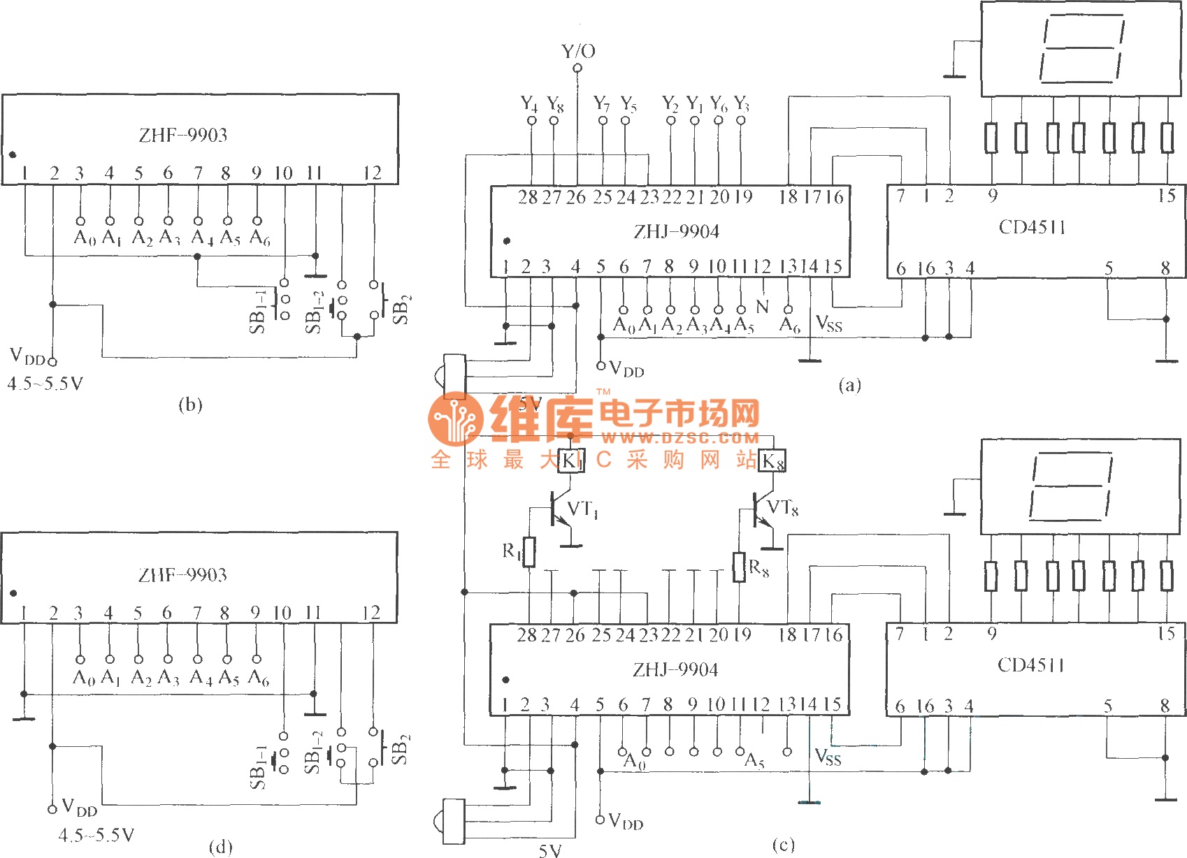
This is an eight-way signal remote control selection circuit composed of ZHJ-9904. It includes a remote control transmitter circuit, an eight-way switch control circuit, and a remote control transmitter. The eight-way signal remote control selection circuit utilizing the ZHJ-9904 is...
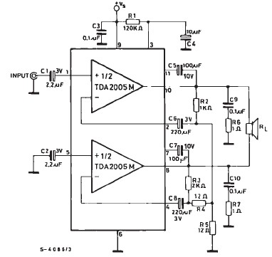
TDA2005 car audio amplifier circuit diagram electronic project using few external electronic parts The TDA2005 is a robust integrated circuit designed for audio amplification in automotive applications. This circuit diagram outlines a project for a car audio amplifier that utilizes...
The circuit consists of two 555 timer oscillators configured in a dual timer arrangement, both set up in astable mode. Components include a 1N4148 diode and a 555 integrated circuit. The dual 555 timer circuit operates in astable mode, generating...
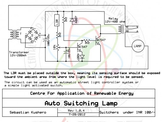
The circuit is designed to switch off a specific lamp or a group of lamps based on varying ambient light levels. Once constructed, it will turn off a lamp at dawn and turn it on at dusk. The power...
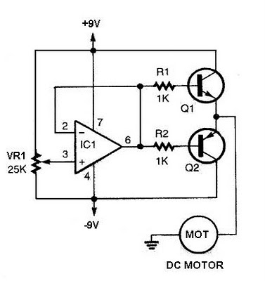
The speed increases in either direction as the potentiometer VR1 is adjusted toward its ends. The TIP3055 Q1 NPN power transistor has a collector current specification of 15A and a VCE0 rating of 60V DC. The MJE34 Q2 PNP...
On a mountain bike, a common issue with traditional flashing LED lights from stores is the frequent problem of flat batteries and lights detaching. As an electronics student, a better solution was sought. A front wheel with a built-in...