
Lead-Acid Battery Charger circuit diagram
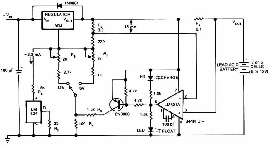
The Lead-Acid Battery Charger circuit operates by utilizing the LM301A operational amplifier as a comparator. The circuit is designed to maintain an optimal charging regime for lead-acid batteries, ensuring longevity and efficiency. The voltage drop across resistor R1 is compared against a stable reference voltage of 18 mV, which is established by resistor R2. When the charging current flowing through R1 falls below 180 mA, the comparator's output signals the voltage regulator to reduce the output voltage to a float level, thus preventing overcharging.
The difference in voltage between the charge and float states, set at 150 mV, is determined by the resistor ratio of R3 to R4. This configuration allows for precise control over the battery charging process. Visual indicators, such as LEDs, provide real-time feedback on the charging status, enhancing user interaction with the device.
The circuit is engineered to deliver an initial charging voltage of 2.5 V per cell at 25°C, facilitating rapid battery charging. As the battery reaches its capacity, the charging current naturally decreases, prompting the circuit to adjust the output voltage accordingly. The design is versatile, supporting both single-cell and multi-cell configurations, with a maximum voltage rating of 18V, accommodating various battery types including NiCAD.
Power transistors Q1 and Q2 are integrated as series regulators, ensuring stable output during the charging process. The circuit also incorporates LED indicators that visually represent the battery's power level, enhancing usability. The simplicity of the design allows for easy final adjustments, typically requiring only a digital voltmeter for calibration.
Additionally, the circuit can be adapted for use with Ni-CAD batteries, featuring built-in current and voltage limiting mechanisms to preserve battery health. The lamp L1 serves as an additional indicator, illuminating brightly during low battery conditions and indicating charging status. For rechargeable lithium batteries, the charging process is executed at a constant current of 60 mA, with a cutoff voltage of 2.4V per cell to ensure safe operation.
The schematic also includes provisions for a solar-powered mobile phone battery charger, designed to operate effectively with lower voltage sources. Caution is advised against using this charger with batteries that have a voltage equal to or lower than that produced by the solar panel, as this could impair functionality and safety. Overall, the circuit provides a comprehensive solution for charging various battery types efficiently and safely.Lead-Acid Battery Charger circuit diagram. The LM301A compares the voltage drop across R1 with an 18 mV reference set by R2. The comparator`s output controls the voltage regulator, forcing it to produce the lower float voltage when the battery-charging current, passing through R1, drops below 180 mA. The 150 mV difference between the charge and fl oat voltages is set by the ratio of R3 to R4. The LEDs show the state of the circuit. The following diagram is the circuit diagram of Lead-Acid battery charger. This circuit provides an initial voltage of 2. 5 V per cell at 25 ƒ to quickly charge the battery. The charging current decreases as the battery is charging, and when the current drops to 180 mA, the charging circuit reduces the output voltage of. This battery charger circuit is regulated and adjustable to make this circuit able to charge the mosto NiCAD battery.
This circuit will work for single cell or multi battery cell which connected with series/parallel connection. The maximum voltage of the batteries should be 18V maximum. Power transistors Q1 and Q2 are connected as series regulators. This circuit is designed to monitor the level of power capacity at 12V Lead-Acid battery. Battery power level will be indicated by LEDs. This easy circuit makes it possible to monitor the charging process to a higher level. Final adjustsments are simple and easy and the only device required is a digital voltmeter for the. The following diagram is the schematic diagram of Ni-CAD Battery Charger circuit which featured with current and voltage limiting to keep the battery lifetime.
The lamp L1 will be light brightly and the LED will be out when the battery is low and battery charging in progress, but the LED is very bright and the. This battery charger circuit is used for rechargable lithium battery. Charging is accomplished with a constant current of 60 mA for AA cells to a cutoff of 2. 4V per cell, at which point the charge must be terminated. The charging system shown is designed for multi-cell battery pack of 2 to 6 series connected cell. This is the schematic diagram of solar powered mobile phone battery charger. The circuit is designed to charge the battery from a source with a lower voltage. Do not use it to charge the battery with the same or lower voltage than the voltage which is generated by the solar panel.
For proper operation of. 🔗 External reference
Related Circuits
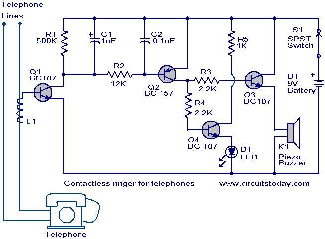
The contactless telephone ringer circuit is designed to produce an audible ring and a visual indication when a call is received. Its primary advantage lies in the absence of direct contact between the telephone line and the circuit, which...
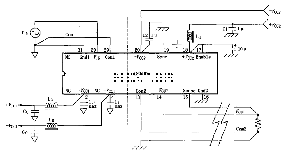
The basic connection circuit for the ISO107 signal and power supply is illustrated. Each power supply terminal must include a bypass filter. If the output current from the isolated power supply exceeds 15 mA, it is advisable to utilize...
SPI Integrated Circuit Bus, IC Buses, an IC, Chip-to-Chip Bus Serial Peripheral Interface, Integrated Circuit Bus types, and IC Bus Electrical Interface Descriptions. The Peripheral Interface (SPI) circuit is a. The Serial Peripheral Interface (SPI) is a synchronous serial communication...
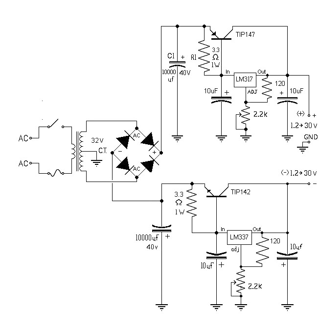
The 10A variable power supply circuit is symmetrical and can provide a symmetrical output voltage ranging from ±1.2 volts to ±30 volts DC, with a maximum current of 10A. This circuit utilizes symmetrical variable voltage regulators LM317 and LM337,...
The voltage to be sampled is applied to the input of R2, a 100K linear taper potentiometer, while the other end of R2 is grounded. Consequently, the signal level that is sent to the buffering level shifter U1-A and...
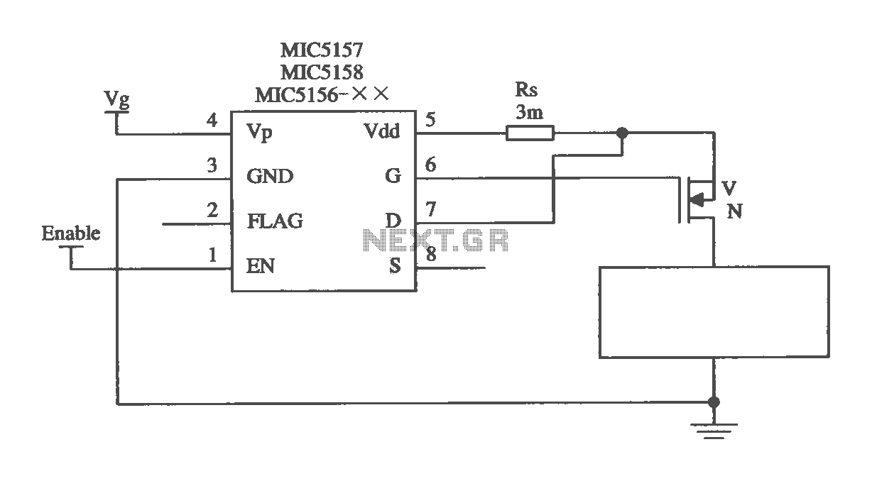
The MIC5156 is a device that incorporates a current limiting function, allowing it to handle high output currents. It can operate with or without a switching regulator circuit. The S terminal is left vacant, and a 16V Zener diode...