
Automatic coming/leaving home light
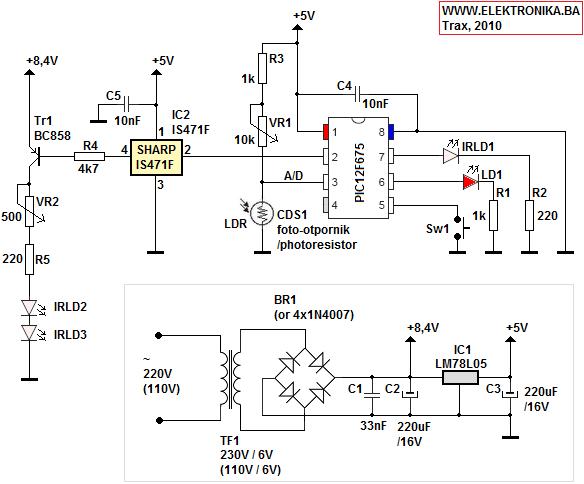
This electronic circuit operates with a dual-channel infrared (IR) remote control system, designed to enhance convenience and energy efficiency in home lighting. The core of the system is the PIC12F675 microcontroller, which processes signals from the ambient light sensor and the IR obstacle detection system. The CdS cell, connected to the microcontroller's analog-to-digital converter (ADC), continuously monitors ambient light levels. This feature is crucial for preventing unnecessary lighting during daylight hours, promoting energy conservation.
For obstacle detection, the system utilizes an IS471F sensor, which provides a trigger signal when it detects motion. The microcontroller responds to this signal by activating the IR LEDs to send the appropriate RC5 codes for turning the lights ON and setting them to SLEEP mode. The SLEEP mode is programmed to deactivate the lights after a specified duration, typically between 1 to 2 minutes, ensuring that lights are not left on unnecessarily.
The inclusion of potentiometers (VR1 and VR2) allows for user adjustments to optimize the system's performance. VR1 adjusts the ambient light threshold, while VR2 fine-tunes the range of the IR obstacle detection. These adjustments are critical for ensuring reliable operation in varying lighting conditions and distances.
The power supply design is also noteworthy, featuring both regulated and unregulated outputs. The unregulated output, derived from a 6V AC source through a bridge rectifier, provides the necessary voltage to drive the IR LEDs, enhancing their range and effectiveness. In contrast, the regulated output ensures stable operation of the microcontroller and other low-power components at 5V.
Overall, this module exemplifies a well-engineered solution for automated lighting control, integrating various electronic components to deliver a functional, user-friendly experience. The thoughtful design considerations, including energy-saving features and modularity, make it a valuable addition to home automation systems.This is a very practical device and I built it so that it is a module to my Dual Channel IR Remote Control. Because of that I ended up with a definite overkill of what is supposed to be a simple switch with a timer when I open/close my door.
Anyway, it is modular+wireless and that`s what I like. - Ambient light level measurement with CdS cell on A/D converter of PIC12F675 so that the lights don`t turn on during the daytime (for power saving feature - we must think green) As I mentioned before, this is an add-on or a hack to my Dual Channel IR Remote Control (IR Remote Switch) project and after reading the description of that project it is clear that for it`s operation IR remote controller is required. No problem here since we can emulate RC5 remote controller with PIC and one IR LED. With this PIC we need to send IR codes for ON and SLEEP functions on every obstacle detection so that the IR Remote Switch turns the lights ON and sets them to SLEEP - meaning that they will turn off in about 1-2 minutes.
That`s about all that this device does, besides measuring ambient light level and it also has a button to send 5 IR codes for programming the IR remote switch. After putting this whole thing together make sure that the RC5 IR LED is pointed to the IR Remote Switch`s TSOP receiver.
Next put IR Remote Switch to programming mode, and press the Sw1 button on this device. Now IR LED will start to send 5 IR RC5 codes that the IR Remote Switch will learn. Those codes are for channel A - ON and SLEEP. In the schematics you can see two potentiometers. One is for setting the range of IR obstacle detection (VR2) and the other one is for the ambient light level (VR1). You must set this light level pot so that the device thinks it is nighttime even if/when the lights in the hallway are ON.
I was lucky with this because CdS cell can recognize this variation in light level. There is also a software threshold when switching from nighttime to daytime that is 4 minutes long. This is enough time to trigger the two RC5 code sending again when the door closes, even when the lights turn on after opening the door for the first time (the IS471F sensor sends the trigger signal twice every time, once the door opens and the other time when they close - mostly quickly after opening them). Here we have two transmitting IR LEDs and IR focus/filter lens on the IS471F receiving sensor. This combination enables more range especially with the external more-powered supply for the IR LEDs.
The PIC microcontroller does all the hard work, it emulates remote controller by sending some custom RC5 codes, measures ambient light level and decides whether it is day or night and receives trigger-signal from the IS471F sensor. On this PCB there is a power supply unit with two voltage outputs. One is unregulated and comes directly from the bridge rectifier. It`s value is around 8. 4V DC and comes from 6V AC multiplied by square root of two (that`s the rule when we rectify from AC to DC).
We need this higher voltage to run those IR LEDs for the obstacle sensor and this way we get more power from them - hence more range. The other voltage source is regulated with LM78L05 down to 5V. Now when I come home at night - the lights turn on immediately after I started opening the door AND when I leave home I don`t need to turn them off because they will turn off automatically!
🔗 External reference
Related Circuits
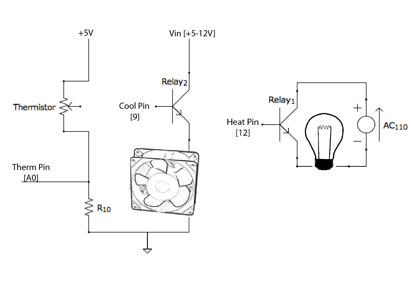
Based on a manual PCR machine constructed a few weeks ago, the Light Bulb PCR machine utilizes a light bulb and an old computer fan as its heating and cooling elements. Instead of the switches shown previously, the unit...
Here is a schematic of a rechargeable 9-LED flashlight using two Gates SLA cells and nine LEDs. It is as bright as when the single bulb was used, and lasts 3 times longer per charge. That is about 10...
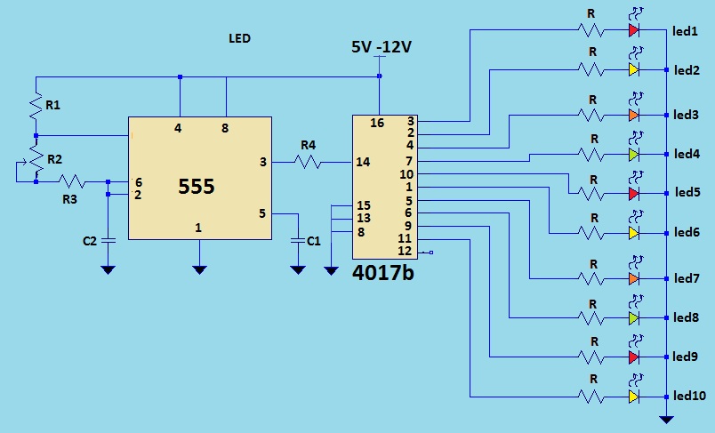
This is a LED sequencer circuit where 10 LEDs light up and turn off sequentially, creating a chasing effect. This simple circuit is suitable for designing lighting decorations on Christmas trees. It can also be used for lighting animations...
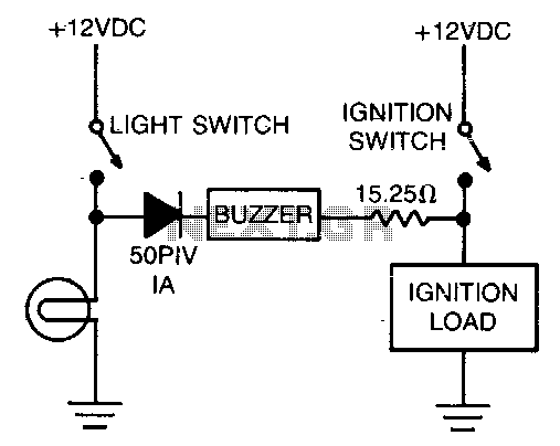
The alarm consists of a diode, buzzer, and a limiting resistor. The diode functions as a switch that enables the buzzer to activate only when the light switch is closed and the ignition is turned off. The circuit described utilizes...
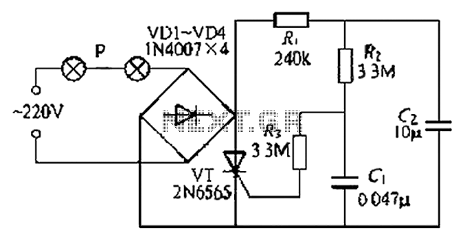
A simple and easy-to-implement one-way flashing lights string controller is designed for small shop or home decoration. This device utilizes a thyristor-based dimmer circuit, which operates effectively by managing large capacitance. The circuit includes a ten-microfarad capacitor connected to...
This project describes a new economical solution of home light control systems. The presented home light control system can be used for different sophisticated home applications. The control system consists of a PC, and control circuitry and the electrical...
Warning: include(partials/cookie-banner.php): Failed to open stream: Permission denied in /var/www/html/nextgr/view-circuit.php on line 713
Warning: include(): Failed opening 'partials/cookie-banner.php' for inclusion (include_path='.:/usr/share/php') in /var/www/html/nextgr/view-circuit.php on line 713