
White LEDs Flashlight

The described circuit is a rechargeable 9-LED flashlight powered by two Gates SLA cells. The design utilizes nine high-brightness LEDs, which collectively provide illumination comparable to that of traditional incandescent bulbs while extending operational time significantly, achieving approximately 10 hours of bright light and an additional 10 hours at reduced brightness. This performance is attributed to the inherent characteristics of LEDs, which maintain illumination levels even as supply voltage decreases, due to the sharp increase in LED resistance.
The circuit employs an LM350 linear voltage regulator to manage current flow to the LEDs. This regulator is advantageous for maintaining consistent brightness across the LED array. Each LED is paired with a small-value series resistor to help balance current distribution, essential when multiple LEDs are connected in parallel. The LM350 introduces a voltage drop of approximately 1.2V, which must be factored into the overall circuit design.
Future iterations of this design plan to incorporate an expanded LED array of 36 units, mounted on a salvaged circuit board from an infrared illuminator. This will be housed within a larger flashlight reflector that accommodates a 6V battery system. The reflector's size is necessary to accommodate protruding components from the PCB while ensuring that all LEDs are aligned for optimal light output. To achieve proper current regulation, a resistance of 125 ohms is recommended for each LED when operating at 6VDC, yielding a current of 24 mA from a fully charged battery.
The design also considers versatility in brightness control, potentially integrating a switch to selectively activate fewer LEDs for scenarios requiring less light and extended battery life. Additionally, the use of LED driver ICs employing switched capacitor topology is mentioned, though these are typically limited to controlling a smaller number of LEDs and are more suited for compact devices.
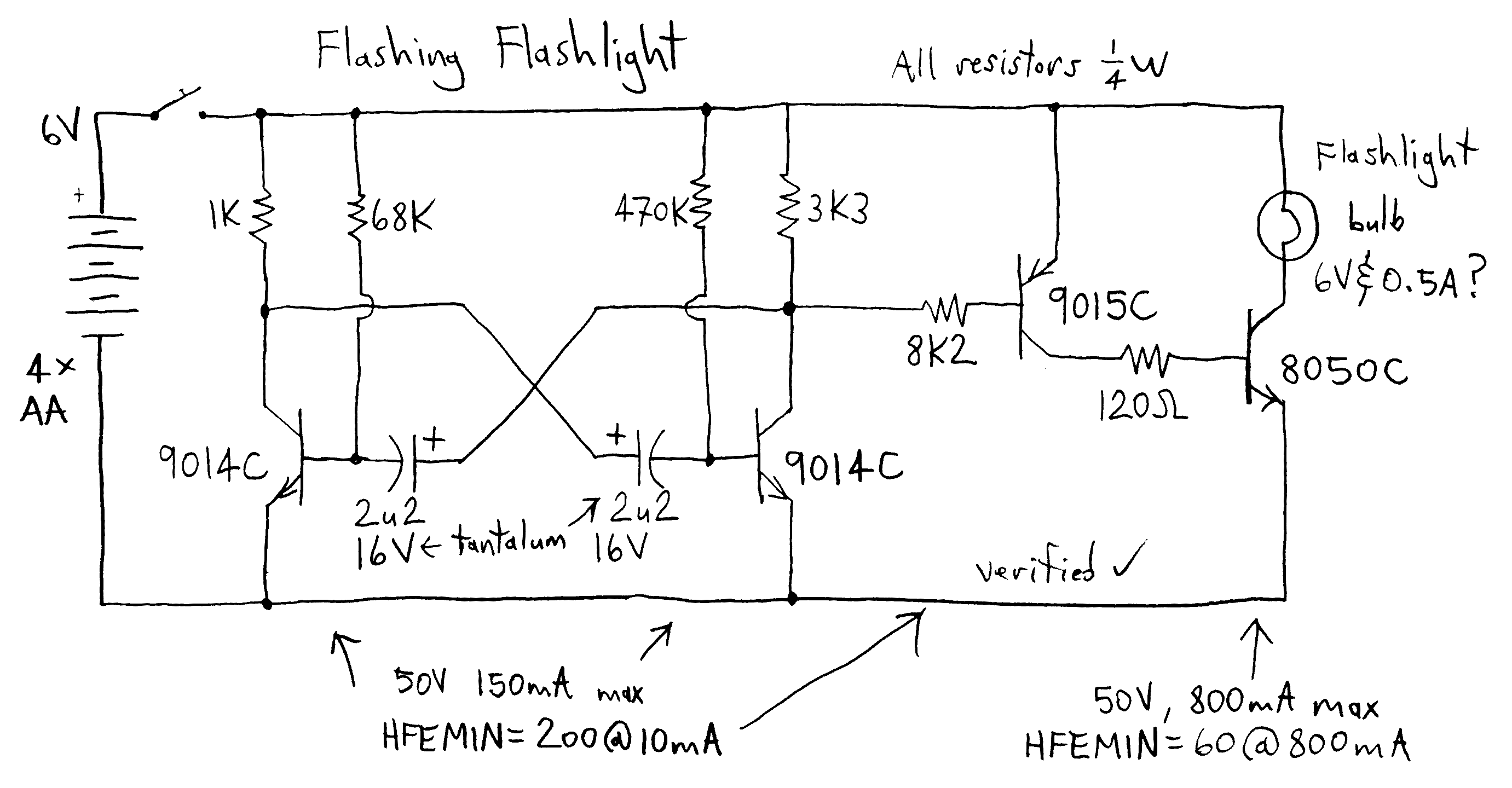
Alignment is critical for achieving a focused beam from the LED array. The physical characteristics of the LEDs, particularly any irregularities at their bases, necessitate careful mounting on the circuit board. Custom spacers or standoffs can be employed to facilitate proper alignment, ensuring that the light output remains uniform and directed.Here is a schematic of a rechargeable 9-LED flashlight using two Gates SLA cells and nine LEDs. It is as bright as when the single bulb was used, and lasts 3 times longer per charge. That is about 10 hours of bright light, at a lower brightness, is available for about 10 hours more (at the risk of abusing the rechargeable cells). At that point, the regular bulb would have long ago gone dark. LED flashlights continue to produce usable light for so long because the resistance of the LED increases sharply as the voltage decreases below a certain point, yet the LED continues to produce light.
At the time that flashlight was built in 2002, the brightest LEDs reasonably available were rated at 6000mCd. Things are only getting better. Note: when the supply voltage is close to the LED voltage, the resistance value is more critical and difficult to select. There are other ways to limit the current, using a PWM or linear curent regulator, and this will be left to the reader to examine.
The LM350 linear IC regulator can be configured to limit the current precisely. If you are using such a regulator with several LEDs in parallel, each will have to have a small-value series resistor, to help equalize the current through the array (unless you want to use 9 IC regulators!). Also be aware that a simple regulator like the LM350 has a certain amount of voltage drop across it (about 1.2V) in order to operate.
The next design in the works will use an array of 36 LEDs, mounted on a 2" diameter circuit board salvaged from an IR illuminator which was part of a security system. This will be placed inside the 5" reflector of a larger flashlight of the type which uses a 6 volt "lantern battery".
The reason that a much larger reflector is needed, is because the resistors stick out the back of the improvised PCB, and it all has to fit inside the cone-shaped area of the reflector. The reflector is not really needed, since almost all the light fires straight out the fronts of the LEDs.
With 6VDC, 125 ohms is a good resistance for each LED. When the battery is new, and putting out about 6.4VDC, current will be 24 mA, within acceptable limits. This would be a very good place to put an LM350 current regulator in series with the array, and a 47 ohm resistor in series with each LED to equalize the current.
This array will consume 700-800mA just like the original incandensant bulb. I am looking for brightness here, not battery life, althought I am considering an extra switch so I can select a few (7 or 9?) LEDs in the center of the array when I want less light and longer battery life. If you use an LM350, the current limiting resistance can be changed to adjust the light output as well.
Some companies make LED driver ICs which use a switched capacitor topology to deliver a precise current to an LED. Most of these, however, are small surface mount parts, and can control only 4 LEDs. They find application in cellphones and other small electronics devices and are very efficient. One thing to observe when making an array of LEDs is alignment. They all need to point exactly the same way if you want a tight beam. LEDs often have little 'bumps' on the heads next to the LED body base. This makes it a bit tough to fit them flat to a circuit board. Small standoff/spacers made for the purpose can be bought or made. The LEDS I got from LEDTRONICS don't have these 'bumps' and fit nicly to the PCB. 🔗 External reference
Related Circuits
As a keen cyclist I am always looking for ways to be seen at night. I wanted something that was a novelty and would catch the motorists eye. So looking around at my fellow cyclists rear lights, I came...
Pretty nice design for a cheap consumer grade flashlight. The power switch was not exactly as shown since there was an option to have the lamp on solid. The described flashlight features a simple yet effective design aimed at consumer-grade...
Here is the schematic, PC board pattern, and parts placement for a "Fantastic Atom Expander". This circuit produces an "exploding atom" effect using 98 LEDs. The LEDs can be any colour but blue. For a very interesting effect, make...
An array of white LEDs can serve as an effective small lamp for the living room. LED lamps are commercially available. LED arrays are increasingly popular for providing ambient lighting in residential spaces. The use of white LEDs in a...
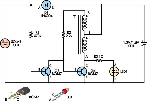
This white LED driver circuit is suitable for garden lighting applications. It automatically activates the LED at night and operates from a single 1.2V NiCad cell, which is recharged by a solar cell during the day. The prototype utilized...
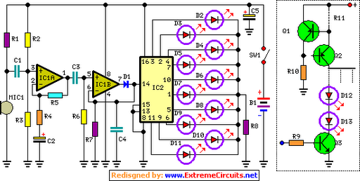
The basic circuit illuminates up to ten LEDs in sequence, synchronized with the rhythm of music or speech detected by a small microphone. The expanded version can drive up to ten strips, each consisting of up to five LEDs,...