
Automatic Cooler Fan Circuit for Amplifiers

The automatic cooler fan circuit for amplifiers operates by utilizing temperature sensors to monitor the heat generated by the amplifier during operation. When the temperature exceeds a predetermined threshold, the circuit activates a cooling fan to dissipate heat, thereby preventing overheating and enhancing the longevity of the amplifier.
The circuit typically includes a temperature sensor, such as an NTC thermistor or a thermocouple, which detects the temperature of the amplifier. The output from the temperature sensor is fed into a comparator circuit, which compares the sensor output with a reference voltage. If the temperature surpasses the reference level, the comparator activates a relay or a transistor switch that powers the fan.
In addition to the basic components, the circuit may include a delay timer to prevent the fan from turning on and off rapidly, which could lead to wear and tear. The timer allows the fan to remain operational for a specified duration after the amplifier has cooled down below the threshold temperature, ensuring efficient cooling without unnecessary power consumption.
The design can also incorporate features such as adjustable temperature thresholds and fan speed control, allowing for customization based on the specific requirements of the amplifier being used. This circuit is particularly beneficial in high-power amplifiers where heat generation is significant, ensuring optimal performance while minimizing energy usage.Automatic cooler fan for amplifiers is a circuit introduced for the purpose of saving power in amplifier circuits. This circuit switches ON. 🔗 External reference
Related Circuits
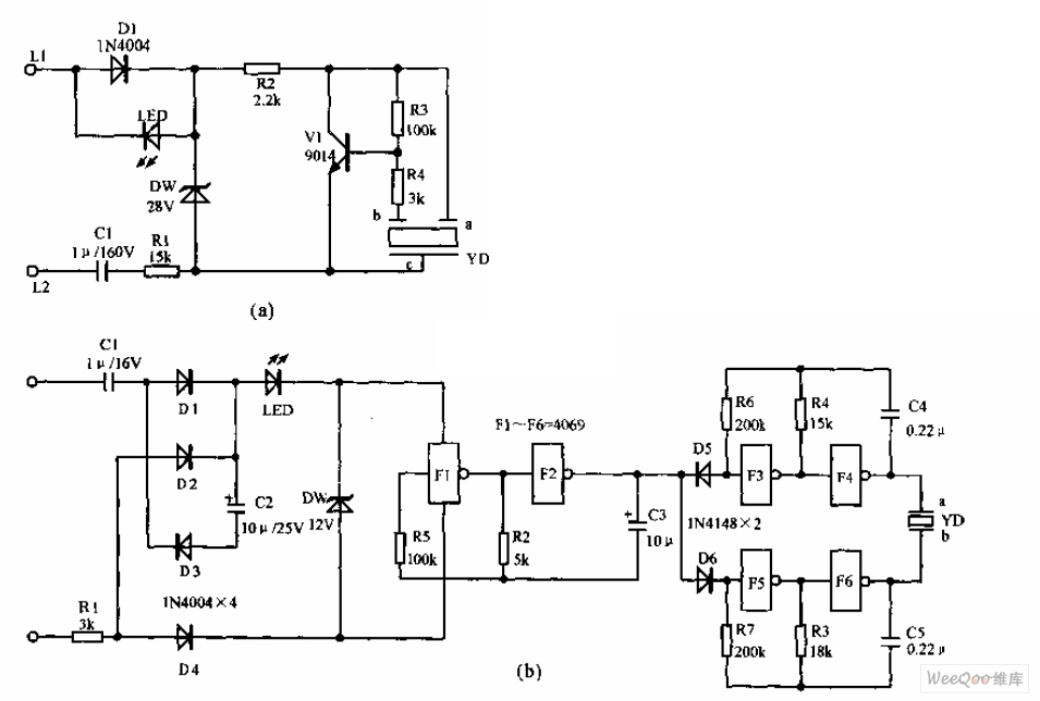
The telephone electronic ringer circuit is illustrated in the provided figure. It features an NPN transistor (either 9014 or 3DG12) as the primary component. The sound device, referred to as YD, functions as both a feedback device and is...
This is a car alarm simulator that uses an LED as a simulation output. This simple circuit can indicate whether a car is running or not by detecting the voltage difference when the car is on or off. This...
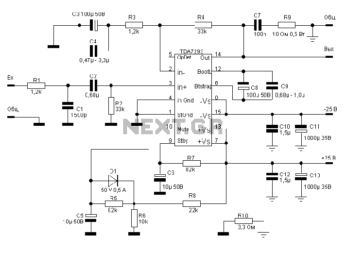
The TDA7293, produced by the ST (SGS-THOMSON) company, is a high-power, high-voltage DMOS high-fidelity amplifier integrated circuit (IC) with a rated output power of 100W. It operates at a maximum voltage of 120V. The key specifications include a dual...
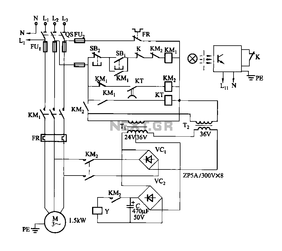
Figure 3-142 illustrates the reel control circuit. The coiler is utilized for winding plastic banding, such as grafting tape, onto a plastic reel. To prevent the plastic tape from being pulled off due to its low tensile strength, the...
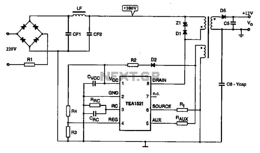
A typical DVD switching power supply circuit is shown in the standby power supply circuit of digital products. It utilizes a switching power supply structure, with the oscillation switch IC EA1623 providing oscillation pulses to the transformer. The secondary...
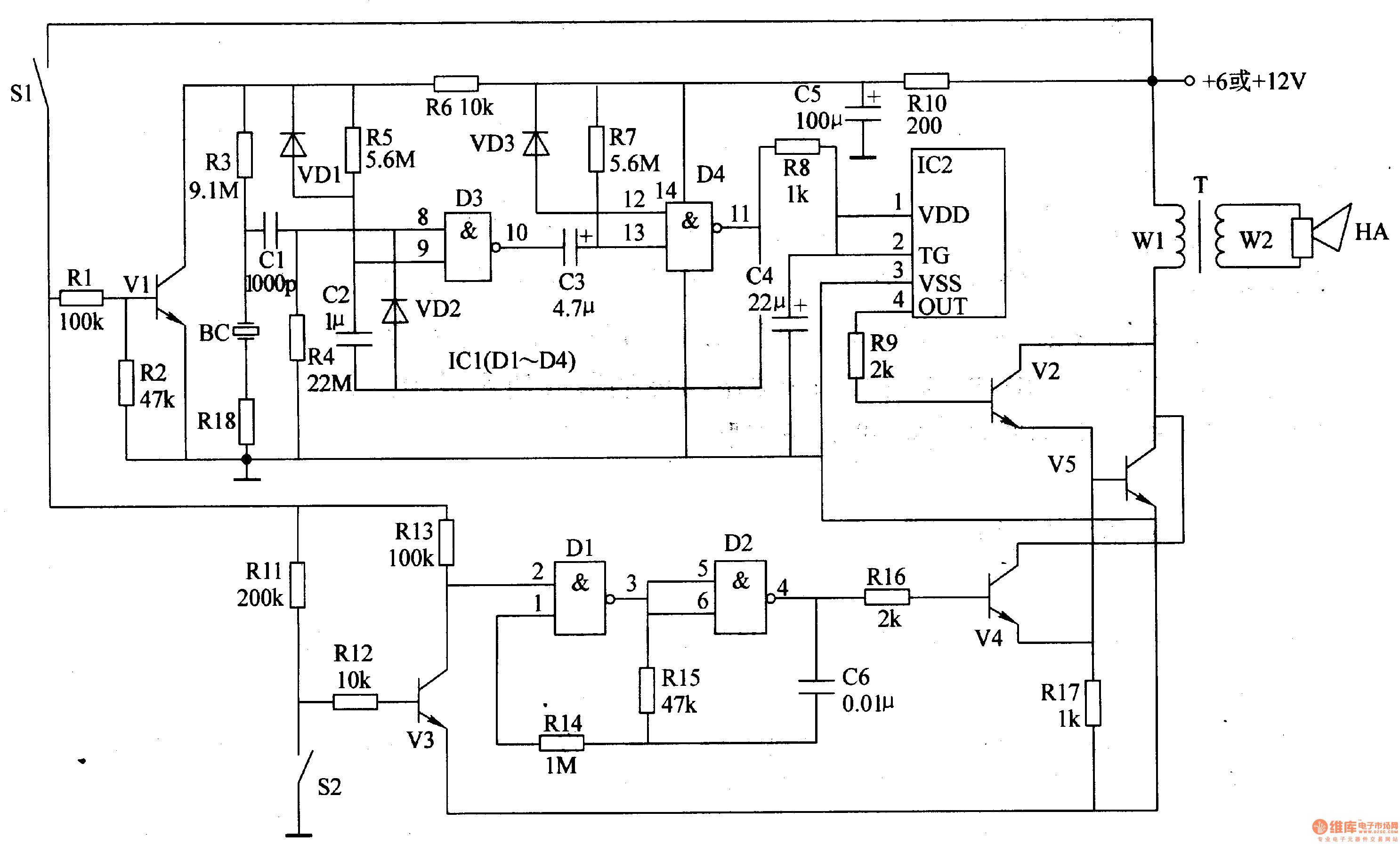
The motorcycle anti-theft alarm circuit consists of several components, including the anti-theft detection circuit, the control circuit, the sound generator, the audio oscillator, and the power amplifier output circuit, as illustrated in figure 7-91. The anti-theft detection circuit is...