
Automatic cycle switch circuit 2
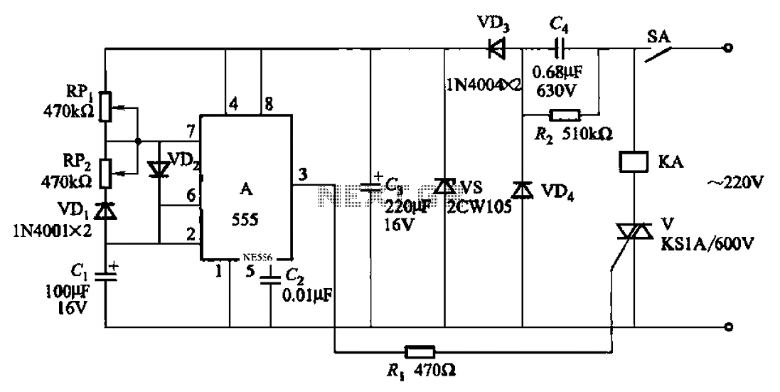
The automatic cycle switch circuit is designed around the versatile 555 timer IC, which functions in astable mode to generate a square wave output. This output controls a bidirectional thyristor, which in turn modulates the power delivered to connected relays or loads. The circuit effectively turns the relay on and off based on the timing parameters set by the potentiometers.
The capacitive step-down circuit is implemented to ensure that the voltage applied to the 555 timer is within its operational limits, thereby enhancing its reliability and performance. The choice of a thyristor allows for efficient switching with minimal power loss, making it suitable for applications where energy efficiency is paramount.
Adjustment potentiometers RP1 and RP2 play a crucial role in fine-tuning the operation of the relay. By varying the resistance values, the timing characteristics of the relay can be altered. For example, increasing the resistance of RP1 to 300kΩ extends the pull-in time to 20 seconds, while a resistance of 220kΩ at RP2 results in a release time of 15 seconds. This flexibility makes the circuit adaptable to various operational requirements.
Overall, this automatic cycle switch circuit represents a practical solution for applications requiring controlled switching of electrical loads, with the added benefit of timing adjustments to suit specific operational needs. Automatic cycle switch circuit 2 It uses 555 IC as the control element} A capacitive step-down circuit; bidirectional thyristor V control relays or loads on and off time. RPi a djustment potentiometer and RP2 (or Cl), respectively, can be changed relay KA pull and release time. As will RPi raised 300k, 0, RPz adjusted 220kfl, the pull-in time KA 20s, the release time is 15s.
Related Circuits
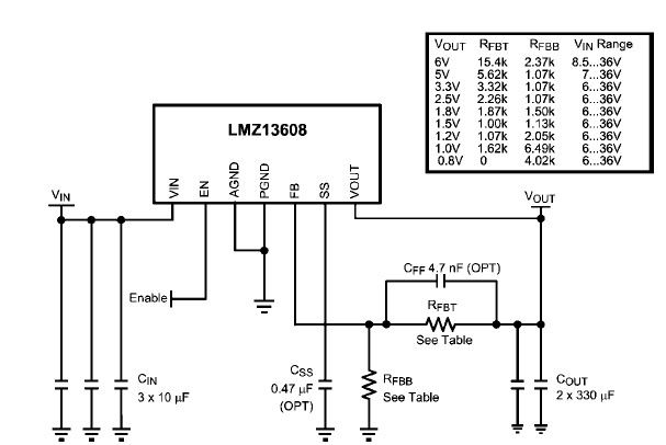
A simple, high-efficiency switching power supply circuit can be designed using the LMZ13608 8A regulator. This regulator offers very high efficiency and requires few external components. It supports a wide input voltage range of 6 to 36 volts and...
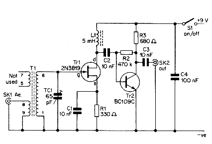
This simple aerial booster circuit design could serve as an alternative or a hobby project for creating an aerial booster device for Citizen Band (CB) radio. The aerial booster circuit is designed to enhance the performance of Citizen Band (CB)...
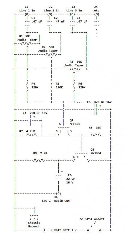
If two of these circuits are made in the same enclosure for stereo, then there can be a single power supply to run both of them. There should be a resistor in series with the incoming 9V+ lead so...
The circuit is designed to create a universal infrared switch with a single channel and ON/OFF functionality, operating in the frequency range of 36 kHz to 38 kHz, suitable for remote control applications. Infrared is a segment of the...
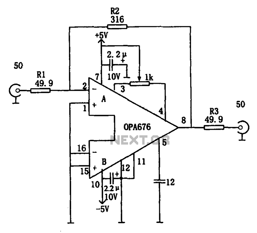
The circuit features a broadband video amplifier with a 50-ohm input/output impedance. To ensure optimal signal transmission and minimize reflected signals, it is often necessary to match the input and output impedances of the amplifier. The broadband video amplifier...
This compact video transmitter is highly useful for video surveillance over short distances (up to 100 meters) and is equipped with either a black and white or infrared camera module. The compact video transmitter is designed for efficient video surveillance...