
Having 50 input output impedance wideband video amplifier OPA676 circuit
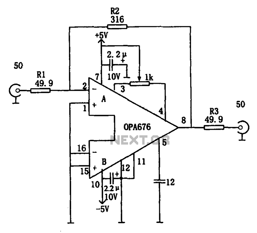
The broadband video amplifier circuit is designed to operate effectively within a frequency range suitable for video signals, typically from 5 MHz to several GHz. The 50-ohm impedance is a standard in RF and video applications, ensuring compatibility with various transmission lines and components.
The amplifier circuit consists of several key components. At the input stage, a matching network may be employed to ensure that the signal from the source is effectively coupled to the amplifier without significant loss or reflection. This network can include resistors, capacitors, and inductors configured to provide the necessary impedance transformation.
Following the input stage, the active amplification element, often a transistor or operational amplifier, is utilized to boost the signal level. The choice of the active device directly impacts the amplifier's bandwidth, gain, and linearity. Proper biasing of the active device is crucial to maintain stability and performance across the desired frequency range.
The output stage of the amplifier also requires careful design to ensure that the output impedance remains at 50 ohms. This can be achieved through additional matching networks or by selecting components that inherently provide the necessary impedance characteristics.
Overall, the design of a broadband video amplifier with a 50-ohm input/output impedance involves careful consideration of component selection, circuit topology, and matching techniques to achieve high performance in signal transmission while minimizing reflections and losses. As shown in Fig having a 50 input/output impedance of broadband video amplifier. In order to achieve a match signal transmission, reducing the reflected signal, often require i nput and output impedance are 50 wideband video amplifier. An amplifier can achieve the above requirements As shown in FIG.
Related Circuits
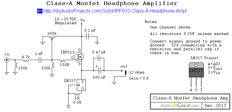
This is a simple and low-cost desktop headphone amplifier designed for office use. The amplifier concept is straightforward and adheres to a typical single-ended Class A circuit. The desktop headphone amplifier utilizes a single-ended Class A design, which is known...
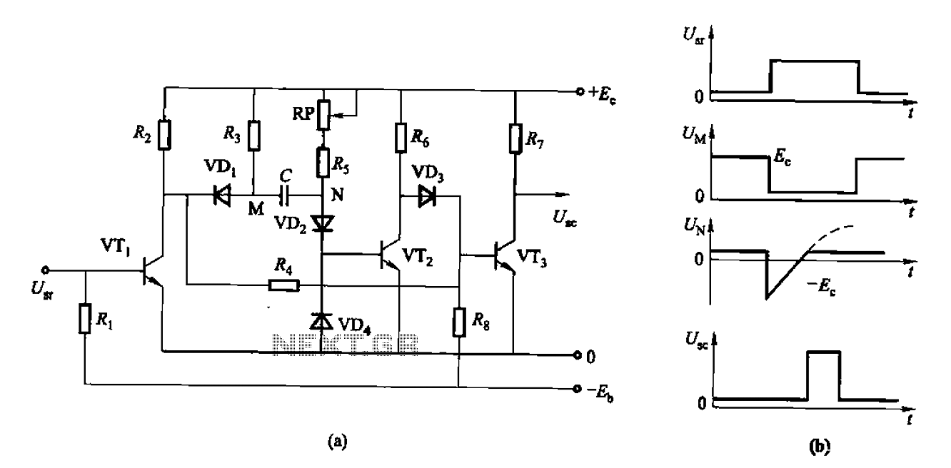
The circuit described is a discharge delay circuit that offers a longer delay compared to a standard rechargeable delay circuit, while also maintaining relatively high accuracy. The schematic diagram illustrates the input and output waveforms. Typically, when there is...
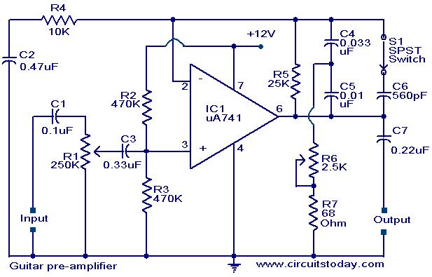
A preamplifier circuit designed for high-impedance electric guitar pickups is presented. This circuit utilizes a uA 741 operational amplifier (IC1) configured as a non-inverting amplifier. The potentiometer R1 functions as a volume control, while potentiometer R6 serves as a...
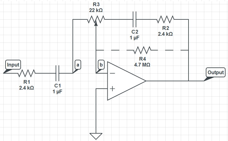
This circuit can function as a treble control circuit, with high-frequency gain occurring when resistor R3 is set to a value that makes points a and b equal (denoted as k=0). Conversely, high-frequency attenuation occurs when R3 is set...
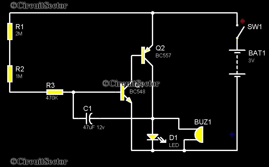
Telephones are declining globally; however, India has over 350 million mobile phone users, alongside a significant number of traditional telephone users. This telephone timer is designed to save costs by controlling unnecessary time spent during phone calls. This simple...
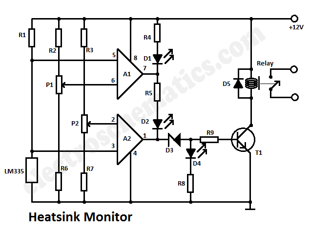
This heatsink temperature monitor circuit uses three LEDs to signal when the temperature exceeds two boundary levels. When the heatsink temperature is below 50 degrees... This heatsink temperature monitor circuit is designed to provide visual indications of temperature levels using...
Warning: include(partials/cookie-banner.php): Failed to open stream: Permission denied in /var/www/html/nextgr/view-circuit.php on line 713
Warning: include(): Failed opening 'partials/cookie-banner.php' for inclusion (include_path='.:/usr/share/php') in /var/www/html/nextgr/view-circuit.php on line 713