
Automatic Dual output Bulb Display
This circuit employs a combination of digital and analog components to achieve a visually appealing sequential lighting effect using ten bulbs. The heart of the system consists of two main integrated circuits: the CD4510 BCD up/down counter (IC2) and the CD4017 decade counter (IC3). The CD4510 counter operates as a BCD counter, allowing it to count from 0 to 9 and then back down to 0, while its output is used to control the sequence of the bulbs.
The oscillator formed by gates N1 and N2 provides a clock signal to IC2, enabling it to increment or decrement based on the logic level present at pin 10. The count direction is determined by this input, allowing for dynamic control over the counting process. The output at pin 7 of IC2 is crucial, as it generates a low pulse upon reaching the ninth count, signaling IC3 to toggle its output state.
The CD4017 decade counter is configured as a toggle flip-flop through the feedback from its Q2 output to the reset pin. This configuration ensures that the output at pin 3 of IC3 alternates between high and low states, effectively creating a binary count that corresponds to the counting operation of IC2. When IC2 counts up and reaches nine, IC3's output transitions, prompting IC2 to count down. This cyclical behavior produces a continuous sequence of lighting effects.
The CD4028 one-of-ten decoder (IC4) translates the BCD output from IC2 into a format suitable for driving the bulbs. Each output from IC4 corresponds to a specific bulb, and as IC2 counts up, the outputs sequentially activate triacs that control the power to the bulbs. This process is mirrored in reverse during the countdown operation, which creates an engaging visual display as the bulbs light up in a sequential pattern both forwards and backwards.
Overall, this circuit exemplifies the integration of digital logic and power control components to create an effective and visually stimulating lighting sequence.This circuit lights up ten bulbs sequentially, first in one direc- tion and then in the opposite direction, thus presenting a nice visual effect. In this circuit, gates N1 and N2 form an oscillator. The output of this oscillator is used as a clock for BCD up/down counter CD4510 (IC2). Depending on the logic state at its pin 10, the counter counts up or down. During count up operation, pin 7 of IC2 outputs an active low pulse on reaching the ninth count. Similarly, during count-down operation, you again get a low-going pulse at pin 7. This terminal count output from pin 7, after inversion by gate N3, is connected to clock pin 14 of decade counter IC3 (CD4017) which is configured here as a toggle flip-flop by returning its Q2 output at pin 4 to reset pin 15.
Thus output at pin 3 of IC3 goes to logic 1 and logic 0 state alternately at each terminal count of IC2. Initially, pin 3 (Q0) of IC3 is high and the counter is in count-up state. On reaching ninth count, pin 3 of IC3 goes low and as a result IC2 starts counting down. When the counter reaches 0 count, Q2 output of IC3 momentarily goes high to reset it, thus taking pin 3 to logic 1 state, and the cycle repeats.
The BCD output of IC2 is connected to 1-of-10 decoder CD4028 (IC4). During count-up operation of IC2, the outputs of IC4 go logic high sequentially from Q0 to Q9 and thus trigger the triacs and lighting bulbs 1 through 10, one after the other. Thereafter, during count-down operation of IC2, the bulbs light in the reverse order, presenting a wonderful visual effect.
🔗 External reference
Related Circuits
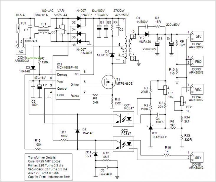
MC44BS373CA: PLL Tuned UHF and VHF Audio Video High Integration Modulator MC44BS373CA The MC44BS373CA Audio and Video Modulator is designed for use in VCRs, set-top boxes, and similar devices. Manufactured by Freescale Semiconductor, Inc. The MC44BS373CA is a highly integrated...
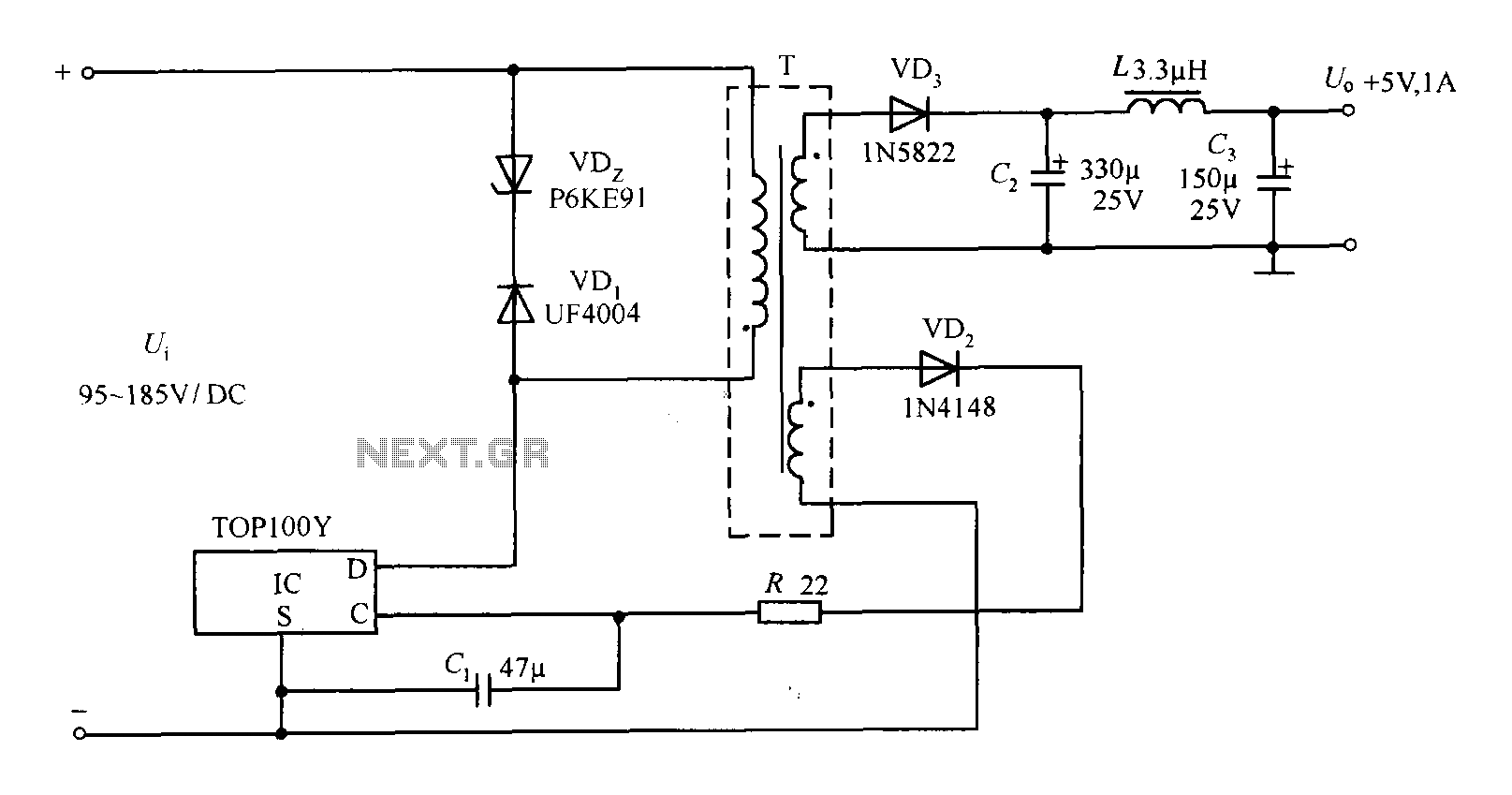
The TOP100Y is a flyback DC switching power supply circuit with a +5V, 1A output. This power supply features a feedback circuit that directly regulates the output voltage, making it suitable for applications that require electrical isolation and minimal...
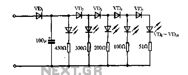
A passive light-emitting diode output level indication circuit. This circuit utilizes a light-emitting diode (LED) to provide a visual indication of the output level from a given source. The design is characterized by its passive nature, meaning it does not...
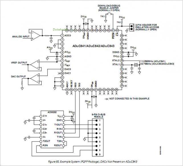
The ADUC845 MicroConverter is a fully integrated dual 24-bit, multi-channel Sigma Delta ADC and flash microcontroller on a single chip. This device is a multi-channel extension of Analog Devices' popular ADuC844 and ADuC846 MicroConverter family and is optimized for...
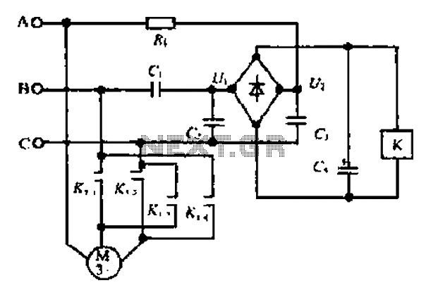
Composition ratio circuit. The circuit consists of resistors and capacitors that form a shift register circuit with diodes VD1 to VD4, creating a bridge for electric current. Capacitor C4 is utilized for filtering applications and for eliminating instantaneous relay...
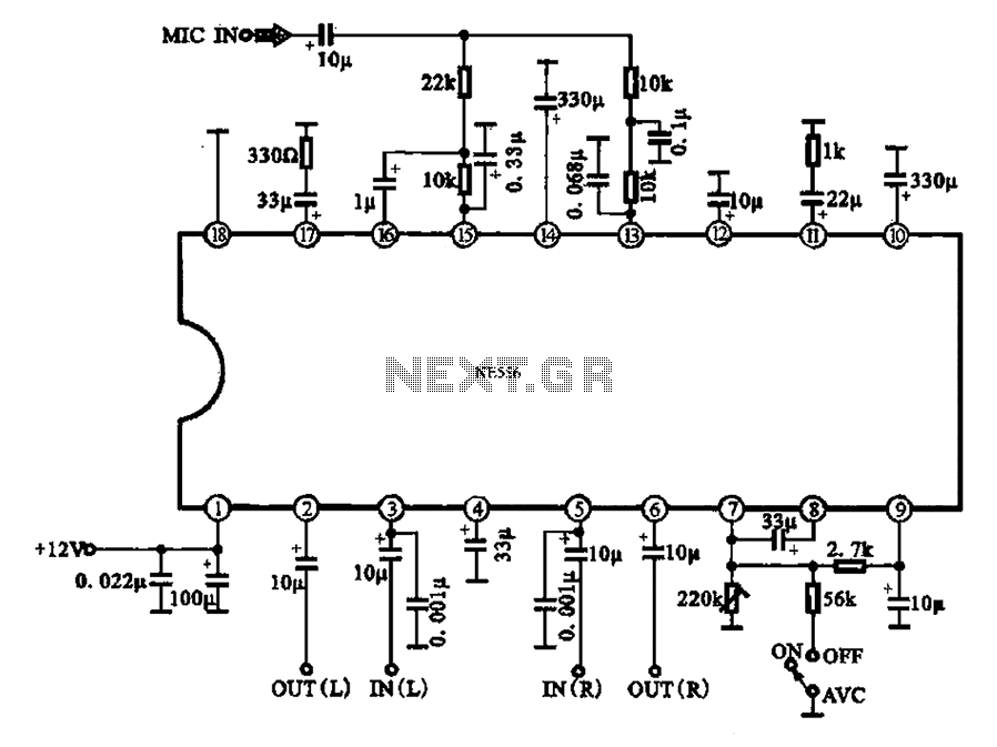
Automatic volume adjustment with ambient noise control circuit. In car stereos and similar devices, the ambient noise level varies during high-speed and low-speed driving or while stationary, leading to different volume requirements. A fixed volume adjustment method may negatively...