
Composite pipe circuit limits bulb cold current of the circuit b

The composite pipe circuit functions as a protective mechanism for electrical components, specifically designed to limit the cold current flowing through a bulb. This is particularly relevant in scenarios where the input signal may be insufficient, potentially leading to inefficient operation or damage to the circuit.
In practical applications, the circuit employs a combination of resistive and reactive elements to stabilize the current flow. The composite pipe, which may consist of various semiconductor materials, operates by adjusting the impedance in response to changes in the input signal. This allows the circuit to maintain a consistent output and prevent excessive current that could otherwise lead to overheating or failure of the bulb.
The protection circuit depicted in Figure 1 typically includes a series of diodes, capacitors, and resistors arranged to form a feedback loop. This configuration ensures that when the input signal drops below a certain threshold, the circuit automatically adjusts to limit the current. Additionally, the use of a composite pipe allows for enhanced thermal management, ensuring that the circuit remains within safe operating temperatures.
In summary, the composite pipe circuit is crucial for maintaining the integrity of the bulb's operation under varying input conditions, providing a reliable solution for cold current limitation and overall circuit protection.Composite pipe circuit limits bulb cold current of the circuit b When the input signal is weak, the use of composite pipe circuit protection circuit shown in Figure 1
Related Circuits

The AC power supply voltage is normal, and a relay is connected to the load (Rfz) circuit. In the event of a load short-circuit failure, the voltage across relay KA drops rapidly, causing KA to release and disconnect the...

A JFET (MPF102) is utilized to chop a DC signal for amplification in an AC-coupled amplifier. Q3 serves as the chopper element, while Q1 and Q2 create a multivibrator to generate the chopping signal. Additionally, resistor Rr establishes the...
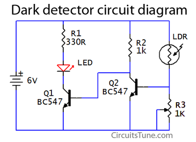
This is a basic dark detector or sensor circuit diagram based on a photoresistor (LDR) and a few components. The dark detector circuit utilizes a photoresistor (LDR) as the primary sensing element. The LDR is a light-dependent resistor that changes...
A touch dimmer circuit is illustrated in the accompanying diagram. It utilizes a finger touch control piece to enable the turning on, off, or stepless adjustment of incandescent lighting. This circuit is applicable in dimming filament lamps and for...
Lamp dimmer. The circuit illustrated below can be employed for dimming lamps. It utilizes a minimal number of components, which can be conveniently installed within the lamp socket. This circuit is typically utilized in RC phase shift configurations. The...

This device functions as a reversal of a radio station, sending a null signal to a selected frequency to eliminate the actual broadcast. The radio transmitter operates at a loss of 10,000W; therefore, this circuit is intended for use...